
Self-ventilation traction motor

A technology of traction motor and self-ventilation, which is applied in the direction of cooling/ventilation device, engine, electromechanical device, etc. It can solve the problems that the ventilation and heat dissipation performance of the traction motor cannot be realized, the automatic lubrication of the drive shaft connection, the poor internal stability of the traction motor, etc., achieve Achieve ventilation and heat dissipation performance, realize high temperature power failure protection, and realize the effect of automatic lubrication

Active Publication Date: 2020-12-25
浙江江宇电机有限公司
View PDF5 Cites 0 Cited by
  • Summary
  • Abstract
  • Description
  • Claims
  • Application Information

AI Technical Summary

Problems solved by technology

[0004] The purpose of the present invention is to provide a self-ventilating traction motor to solve the problem that the existing traction motor proposed in the above background technology cannot realize the ventilation and heat dissipation performance inside the traction motor and the automatic lubrication of the joint of the drive shaft during use. Problems leading to poor stability of traction motors during operation

Method used


Image

  • Self-ventilation traction motor
  • Self-ventilation traction motor
  • Self-ventilation traction motor

Examples


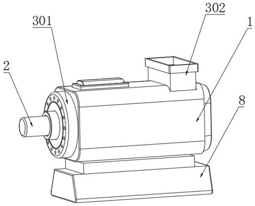
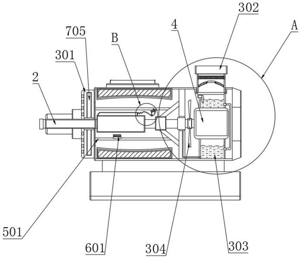
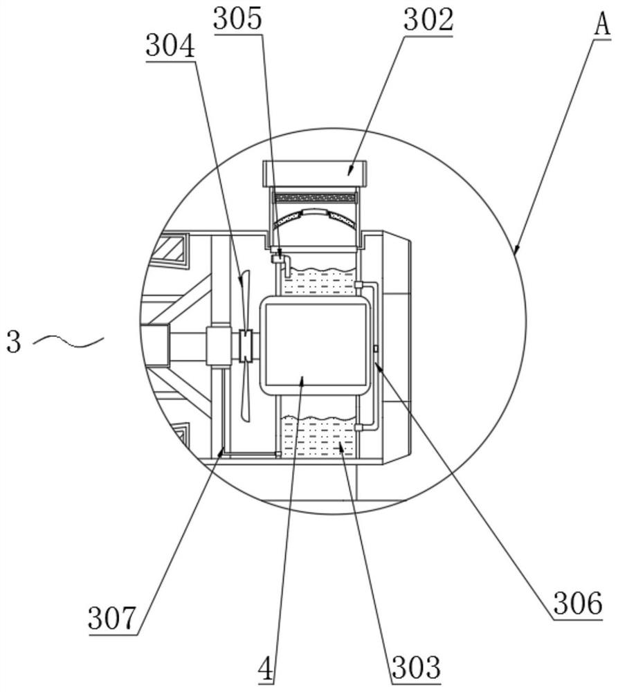
Embodiment Construction

[0027] The following will clearly and completely describe the technical solutions in the embodiments of the present invention with reference to the accompanying drawings in the embodiments of the present invention. Obviously, the described embodiments are only some, not all, embodiments of the present invention. Based on the embodiments of the present invention, all other embodiments obtained by persons of ordinary skill in the art without making creative efforts belong to the protection scope of the present invention.

[0028] refer to Figure 1-Figure 6 , wherein a self-ventilating traction motor includes a housing 1, a drive shaft 2 and a rotor 4, the rotor 4 is connected to one side of the housing 1, the drive shaft 2 is connected to one end of the rotor 4, and a ventilation mechanism 3 is installed inside the housing 1 A noise reduction mechanism 5 is installed on the outside of the drive shaft 2, and a power-off mechanism 6 is installed on the inner wall of the noise red...


PUM


Abstract

The invention discloses a self-ventilation traction motor. The motor comprises a shell, a driving shaft and a rotor; the rotor is connected with one side of the interior of the shell, the driving shaft is connected with one end of the rotor, an air inlet cover is connected with one side of the exterior of the shell, an air outlet cover is embedded into the top end of one side of the outer wall ofthe shell, and liquid storage hoppers are arranged on the two sides of the outer wall of the rotor respectively. Blades are connected to the top end of the exterior of the driving shaft in a sleevingmode, air inlet pipes are installed at the top ends of one sides of the outer walls of the liquid storage hoppers in an embedded mode, and pressure balancing pipes are installed on one sides of the outer walls of the two liquid storage hoppers. The blades are driven by the driving shaft to rotate, so that external gas is fed into the shell from the air inlet cover; and heat generated in the shellis absorbed. Meanwhile, lubricating oil liquid is injected into the rotary connecting position of the driving shaft from the liquid inlet pipe through the pressure balancing pipes, so that the ventilation and heat dissipation performance of the interior of the traction motor is achieved, and automatic lubrication of the connecting position of the driving shaft is achieved.

Description

technical field [0001] The invention relates to the technical field of motor equipment, in particular to a self-ventilating traction motor. Background technique [0002] Motors used for traction on railway mainline electric locomotives, industrial and mining electric locomotives, electric drive diesel locomotives and various electric vehicles. Traction motors include traction motors, traction generators and auxiliary motors. The working principle of traction motors is the same as that of general DC motors, but there are special working conditions. To withstand considerable shock and vibration. [0003] However, the existing traction motors cannot achieve ventilation and heat dissipation inside the traction motor and automatic lubrication of the connection of the drive shaft during use, resulting in poor stability of the traction motor during operation. Contents of the invention [0004] The purpose of the present invention is to provide a self-ventilating traction motor ...

Claims


Application Information

Patent Timeline
IPC IPC(8): H02K9/06H02K5/16H02K5/24H02K5/10F16N7/00
CPCF16N7/00F16N2210/18H02K5/10H02K5/16H02K5/24H02K9/06
Inventor 李晓宇
Owner 浙江江宇电机有限公司
Learn More