Extraocular muscle training device for vision rehabilitation
A training device and eye-using technology, which can be used in eye exercisers, physical therapy, etc., can solve the problems of delaying training progress and low training efficiency, and achieve the effects of speeding up training progress, improving practicality, and improving training effects
- Summary
- Abstract
- Description
- Claims
- Application Information
AI Technical Summary
Problems solved by technology
Method used
Image

Examples
Embodiment
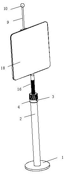
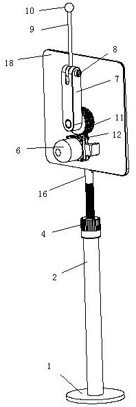
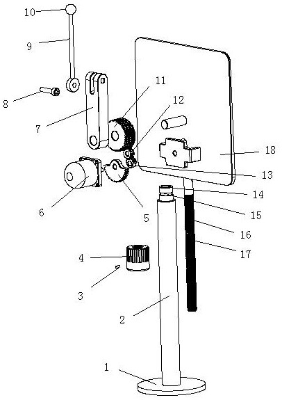
[0023] Such as Figure 1-4 As shown, an extraocular muscle training device for vision rehabilitation includes a base 1 detachably installed on a placement surface, a support column 2 is vertically provided on the base 1, and a shield is provided at the upper end of the support column 2 18. One side of the shutter 18 is horizontally connected with a swing arm 7 by installing a rotating shaft. The swing arm 7 is driven to swing back and forth by a reciprocating swing drive assembly. A thin rod 9 is hinged on the upper end of the swing arm 7. The thin rod 9 is limited by the fastening assembly to rotate along the hinge with the swing arm 7, and its top end protrudes above the shutter 18 and is provided with a swing ball 10.
[0024] As a further optimization of the above-mentioned technical solution, the upper end of the supporting column 2 is rotatably fitted with a rotating sleeve 4, and the coaxial thread on the rotating sleeve 4 is threaded with a threaded rod 16, and the sup...
PUM
 Abstract
Description
Claims
Application Information