

Riveting device for automobile heat insulation part mold
A technology of heat insulator and riveter, applied in the direction of perforation tools, manufacturing tools, forming tools, etc., can solve the problems of position deviation, damage to the company's interests, loss of company order customers, etc., so as to reduce the cost of mold manufacturing and shorten the mold The effect of manufacturing cycle and saving debugging cost
- Summary
- Abstract
- Description
- Claims
- Application Information
AI Technical Summary
Problems solved by technology
Method used
Image

Examples
Embodiment
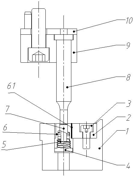
[0018] see figure 1 with figure 2 , a riveter for automotive heat insulation molds, comprising an upper mold part and a lower mold part connected to each other,
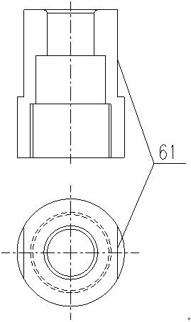
[0019] The lower mold part includes an insert 1, a pressing plate 2, a screw 3, a screw plug 4, a spring 5, a die 6 and an ejector pin 7; the insert 1 has a hole, and the screw plug 4, the spring 5, the concave The mold 6 and the ejector pin 7 are sequentially arranged in the hole from bottom to top, and the insert 1 is also provided with a mounting groove for installing the pressing plate 2 and a mounting screw hole for installing the screw 3, that is, the pressing plate 2 is installed. In the installation groove of the insert 1, the concave mold 6 is also provided with an anti-rotation surface 61, and the pressure plate 2 cooperates with the anti-rotation surface 61; the pressure plate 2 cooperates with the anti-rotation surface 61 of the concave mold 6 In order to achieve the problem of anti-rotation of the die...
PUM
 Abstract
Description
Claims
Application Information