Opening type comfortable handle mold structure

A technology of opening type and mold, which is applied in household appliances, other household appliances, household components, etc., can solve problems such as inability to carry out actual production, and achieve the effect of reducing production efficiency and increasing production cost

Pending Publication Date: 2020-12-29
徐勇
View PDF1 Cites 0 Cited by
  • Summary
  • Abstract
  • Description
  • Claims
  • Application Information

AI Technical Summary

Problems solved by technology

With regard to the utility model patent of "open-type comfortable handle that can rely on elastic contraction and expansion and automatically fit the shape of the hand" with the application number 202021084876.6 submitted by me on June 12, 2020, the inventor also designed this handle first. Mold demoulding structure, and made a test mold after many actual production tests to demonstrate the feasibility before submitting the patent, so the essence of this handle is that the mold demoulding structure must be designed before the handle can be produced, otherwise it will be like Castles in the air generally only have design drawings but cannot be actually produced, so they are meaningless

Method used


Image

  • Opening type comfortable handle mold structure
  • Opening type comfortable handle mold structure
  • Opening type comfortable handle mold structure

Examples


Embodiment approach

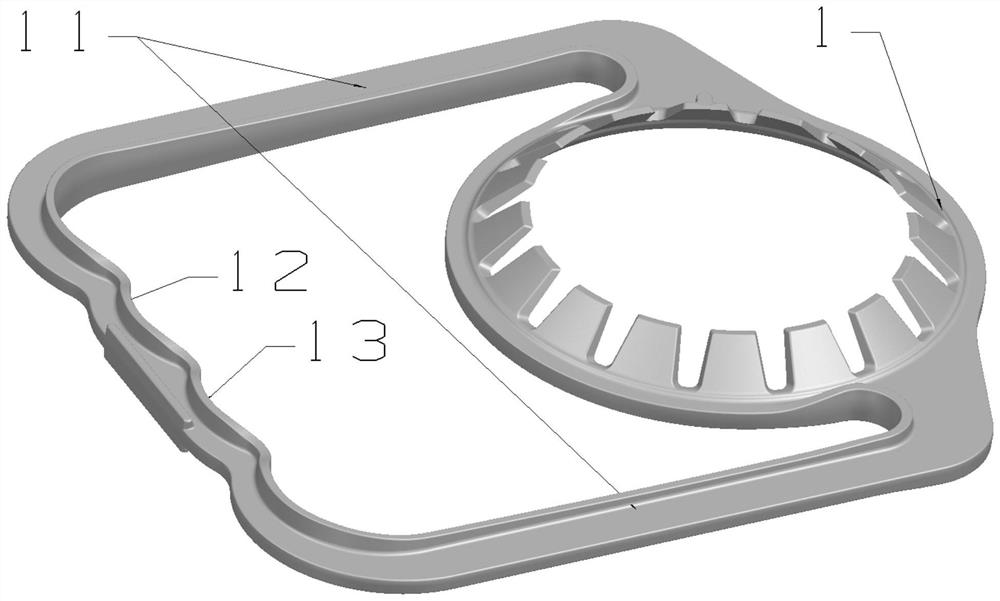
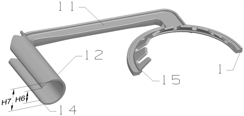
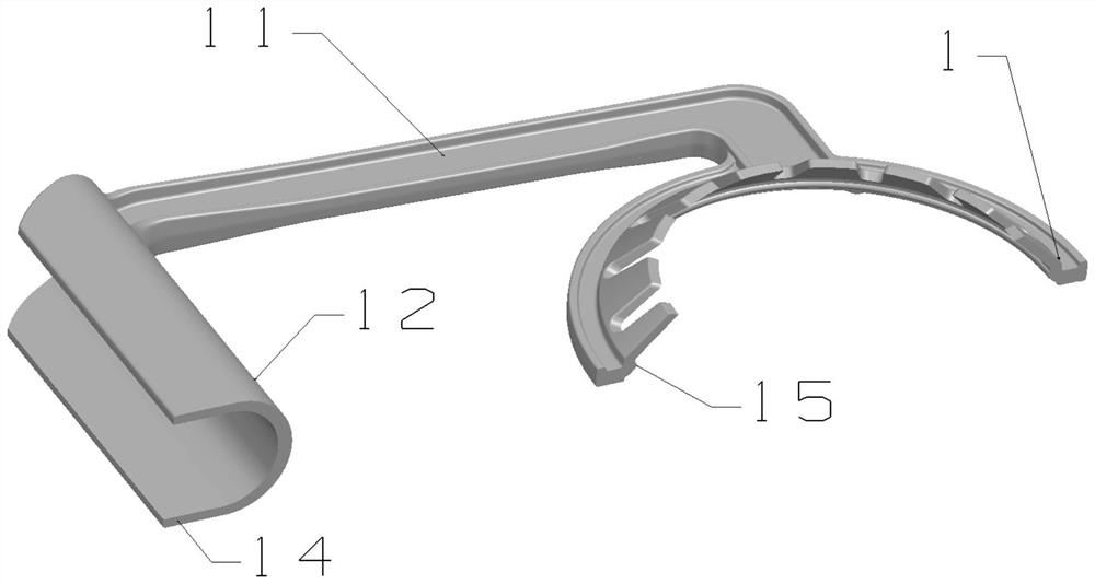
[0048] The first way ( Figure 4-Figure 10 ): the mandrel 4 is installed on the mold static plate group by the positioning mechanism 41, so that it can do a straight line from zero to the demoulding distance relative to the mold static cavity plate 3 ( Figure 5 ) or curved motion ( Figure 8 ), mandrel 4 can also rotate by positioning mechanism 41 ( Figure 7 ), the mandrel 4 will be pressed by the mold static cavity plate 3 and the mold dynamic cavity plate 2 under the mold clamping state, and the distance between the mandrel 4 and the mold static cavity plate 3 is zero ( Figure 4 ), between the mandrel 4 and the mold static cavity plate 3 and the mold dynamic cavity plate 2, the injection space of the annular opening 14 is formed ( Figure 4 ), after the product injection molding is completed, the mold starts to open the mold, and the auxiliary spring 5 is installed between the mandrel 4 and the mold static plate group to promote the mandrel 4 ( Figure 5 ), or use the ...


PUM


Abstract

The invention discloses an opening type comfortable handle mold structure, a lifting handle is divided into a lantern ring part, a lifting handle part and a connecting belt between the lantern ring part and the lifting handle part, wherein the section of the lifting handle part is of an annular opening structure, and a core rod is arranged in an annular opening. The core point of the invention isthat a core rod subjected to mold opening drives the annular opening to form a certain distance H with a mold cavity plate through various mechanical driving structures, the distance can accommodate peripheral expansion generated when the annular opening is separated from the core rod, due to the distance, the annular opening does not interfere with the mold cavity plate when being separated fromthe core rod or does not interfere with the mold cavity plate when being separated from the annular opening as well, and in addition, the various mechanical structures are used for changing the direction when the annular opening is separated from the core rod, so that the direction is closer to the positive demolding direction or the mold opening direction in order to prevent the annular opening from interfering with the cavity plate when the annular opening is separated from the core rod, in addition, a lantern ring inner core is arranged to clamp the lantern ring part in order to enable theannular opening to be pulled by the lantern ring part through a connecting belt when the annular opening is separated from the core rod.

Description

technical field [0001] The invention belongs to the technical field of mold structures, and in particular relates to an open-type comfortable handle mold structure. Background technique [0002] At present, the edible oil, beverage, condiment and other packaging bottles on the market will use a kind of handle to facilitate the user to hold. This kind of handle is generally composed of a collar part 1, a handle part 12, and a connecting belt 11 between them. , the demoulding methods of this handle mold on the market are roughly divided into two types: [0003] One is a handle mold for the production of handles with positive drafts on all sides of the handle (see attached Figure 26 ), the handle part 12 is generally an upright sheet (see attached figure 1 ), which is the most common handle on the market. Each surface of this handle has a positive slope relative to the mold opening direction and the demoulding direction. The demoulding of this handle mold only needs to be do...

Claims


Application Information

Patent Timeline
Patent Type & Authority Applications(China)
IPC IPC(8): B29C45/26B29C33/76B29C45/33B29C45/36B29L31/46
CPCB29C33/76B29C45/2602B29C45/33B29C45/332B29C45/36B29C2045/363B29L2031/463
Inventor 徐勇
Owner 徐勇
Why Eureka
Try Eureka