Loading device and stacking machine

A technology of materials and scissors, which is applied in the field of palletizers, can solve the problems of large manpower consumption, material resources, low efficiency of palletizers, and large push devices, and achieve the effect of reducing volume and improving stacking efficiency

Pending Publication Date: 2020-12-29
SHANGHAI KELAI MECHATRONICS ENG CO LTD +1
View PDF0 Cites 0 Cited by
  • Summary
  • Abstract
  • Description
  • Claims
  • Application Information

AI Technical Summary

Problems solved by technology

However, the available space of the palletizer is relatively narrow, and the ordinary pushing device is relatively large, which is often inconvenient to install on the pushing platform of the palletizer
Moreover, the actual logistics environment is relatively complex. In some relatively narrow spaces, when materials need to be pushed, ordinary push devices cannot be installed in the narrow space. If the transportation equipment is modified to use the push device, it will consume a lot of energy. manpower, material resources
Furthermore, the width of the platform carrying materials cannot be adjusted at present. In order to meet the width of various containers or truck containers, the platform adopts the minimum width size, and the working efficiency of the palletizer is low.

Method used


Image

  • Loading device and stacking machine
  • Loading device and stacking machine
  • Loading device and stacking machine

Examples


Embodiment Construction

[0030] The present invention will be further described in detail below in conjunction with the accompanying drawings and embodiments. It should be understood that the specific embodiments described here are only used to explain the present invention, but not to limit the present invention. In addition, it should be noted that, for the convenience of description, only some structures related to the present invention are shown in the drawings but not all structures.

[0031] In the description of the present invention, unless otherwise clearly specified and limited, the terms "connected", "connected" and "fixed" should be understood in a broad sense, for example, it can be a fixed connection, a detachable connection, or an integrated ; It can be a mechanical connection or an electrical connection; it can be a direct connection or an indirect connection through an intermediary, and it can be the internal communication of two components or the interaction relationship between two ...


PUM


Abstract

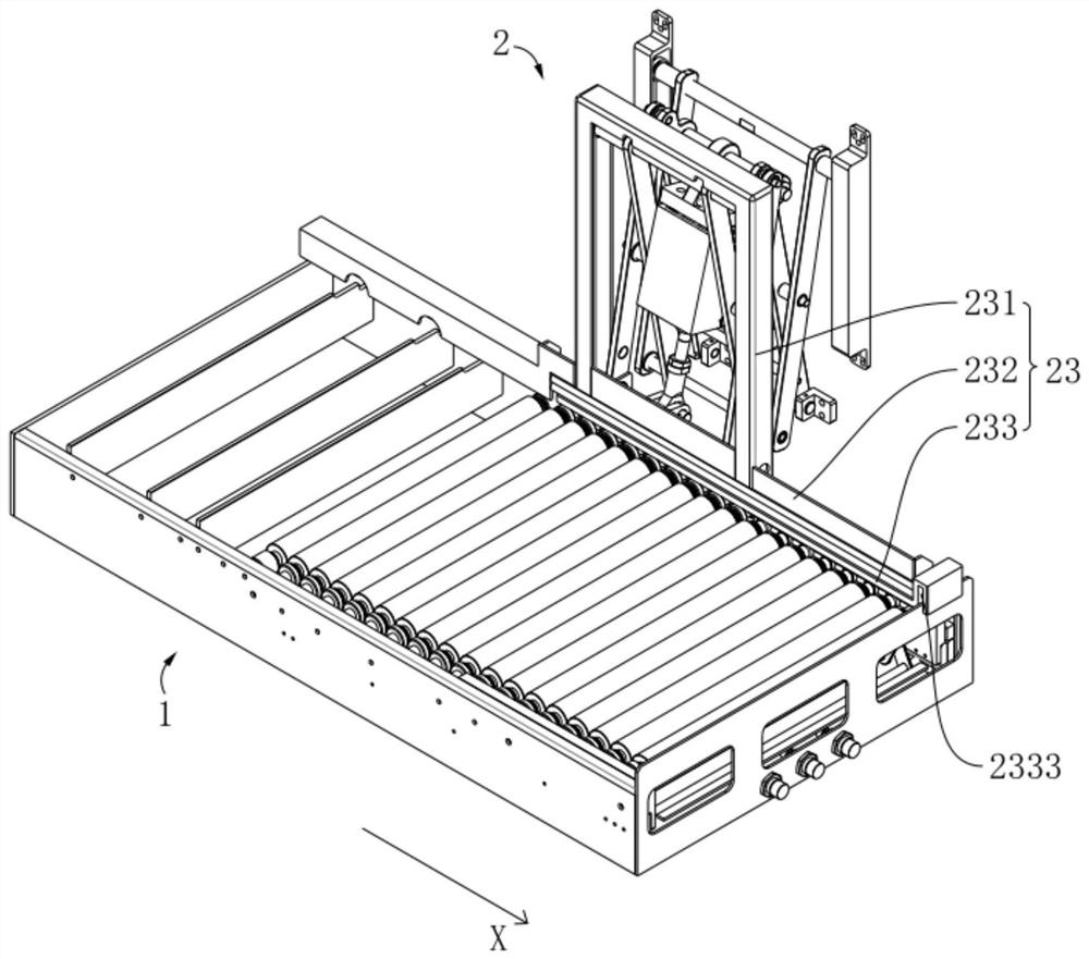
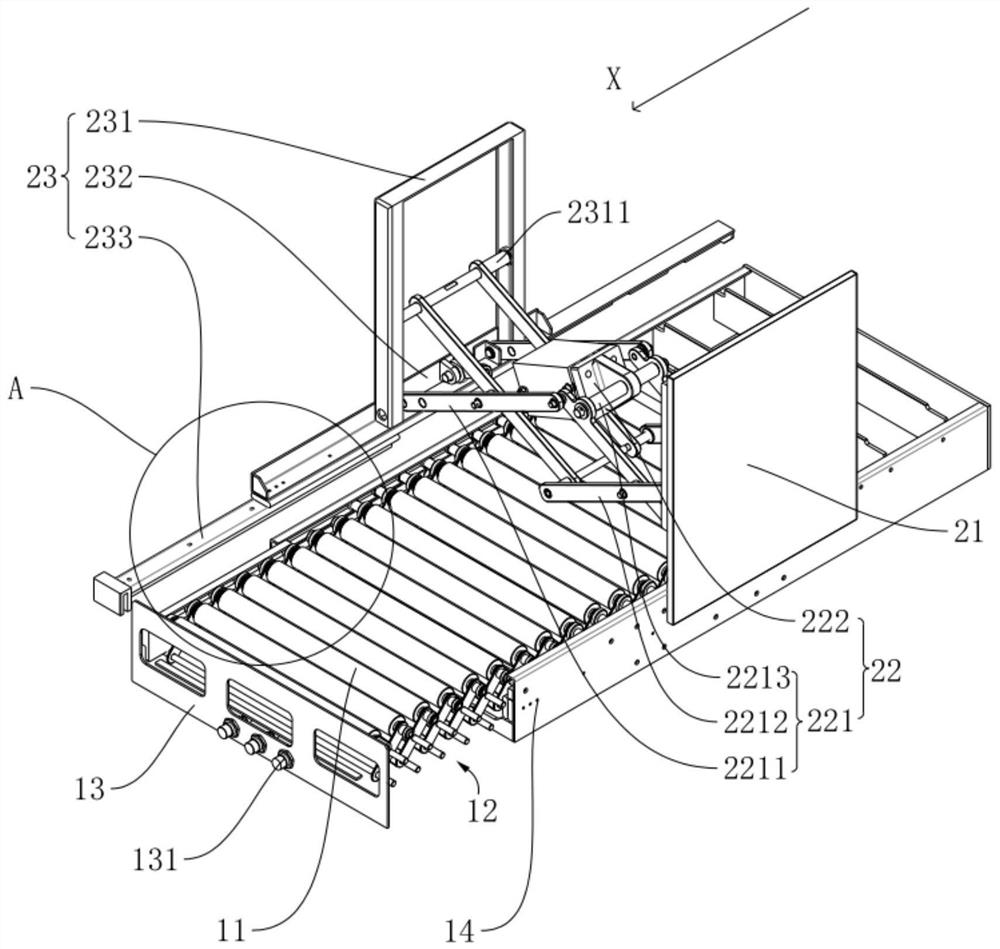
The invention relates to the technical field of stacking machines, and discloses a loading device and a stacking machine. The loading device comprises a supporting table mechanism and a push plate mechanism, wherein the supporting table mechanism is used for bearing materials, and the length of the supporting table mechanism in the X direction is adjustable; the push plate mechanism is arranged ona first side of the supporting table mechanism, and the push plate mechanism is used for pushing off the materials on the supporting table mechanism to the second side of the supporting table mechanism; and the push plate mechanism comprises a side plate, a push plate assembly and a telescopic assembly, the telescopic assembly is mounted on the side plate and is in driving connection to the pushplate assembly, and the telescopic assembly is used for driving the push plate assembly to push off the materials. According to the invention, the placement amount of the materials is increased, and the loading device is suitable for containers or truck containers of various widths, so that the stacking efficiency of the materials is improved, and the push plate mechanism in a narrow space is applied.

Description

technical field [0001] The invention relates to the technical field of palletizers, in particular to a feeding device and a palletizer. Background technique [0002] At present, the development of mechanical automation in the logistics industry is fast. When materials are transported to the end or designated position on the platform, the materials need to leave the platform. Continue shipping on other platforms. For example, many palletizers are equipped with a material pushing device, which is used to push the material out and stack it neatly layer by layer. [0003] In the prior art, the material pushing device is composed of a cylinder, a push rod, and a push plate. When the material arrives, the push plate pushes the material out. However, the available space of the palletizer is relatively narrow, and the common pushing device is relatively large, which is often inconvenient to be installed on the pushing platform of the palletizer. Moreover, the actual logistics env...

Claims


Application Information

Patent Timeline
Patent Type & Authority Applications(China)
IPC IPC(8): B65G57/11
CPCB65G57/11
Inventor 刘宗阳苏建良杨文涛谈士力沈俊杰何永义
Owner SHANGHAI KELAI MECHATRONICS ENG CO LTD
Why Eureka
Try Eureka