Counterweight side-falling elevator structure

An elevator and redirection technology, which is used in elevators in buildings, lifting equipment in mines, transportation and packaging, etc., can solve the problem of increasing the difficulty of positioning components such as load-bearing beam traction machines, the large inclination of the traction machine, and the increase in Difficulty in installation of related components in elevator machine room

Pending Publication Date: 2020-12-29
YUNGTAY ELEVATOR EQUIP CHINA
View PDF0 Cites 0 Cited by
  • Summary
  • Abstract
  • Description
  • Claims
  • Application Information

AI Technical Summary

Problems solved by technology

The placement position of the counterweight 4 should avoid interference with the operation of the car door panel assembly 3, the traction wheel 7 and the guide wheel 8 of the machine room above the placement position of the counterweight 4 should be placed obliquely, and the traction frame 11 should be placed obliquely on the load-bearing beam 10. Such

Method used


Image

  • Counterweight side-falling elevator structure
  • Counterweight side-falling elevator structure
  • Counterweight side-falling elevator structure

Examples


Embodiment 1

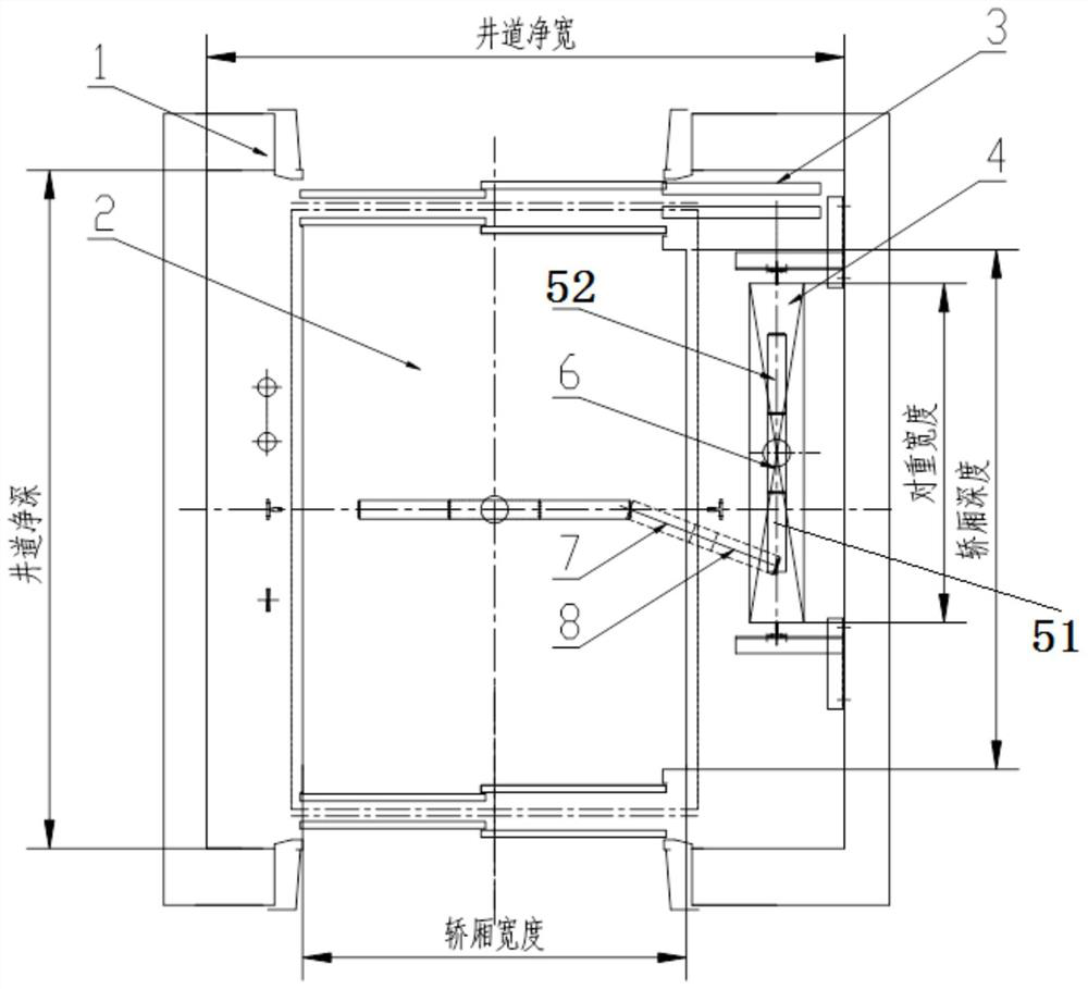
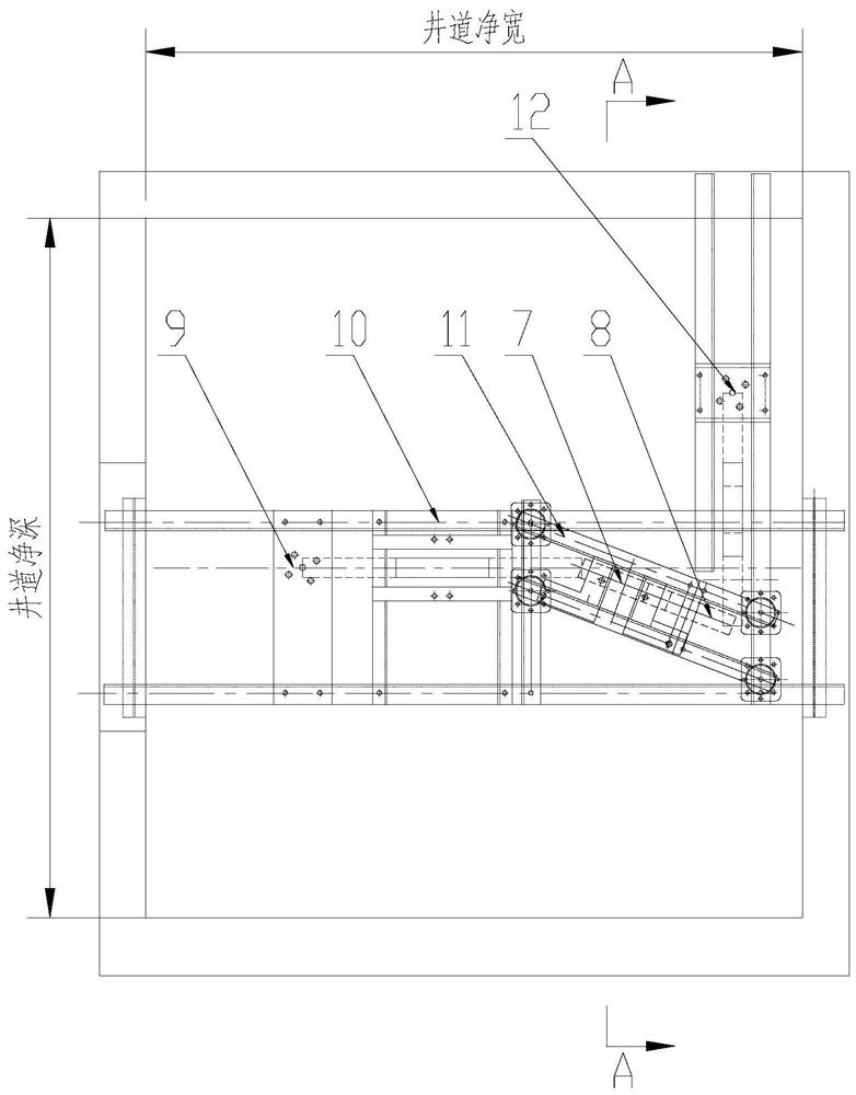
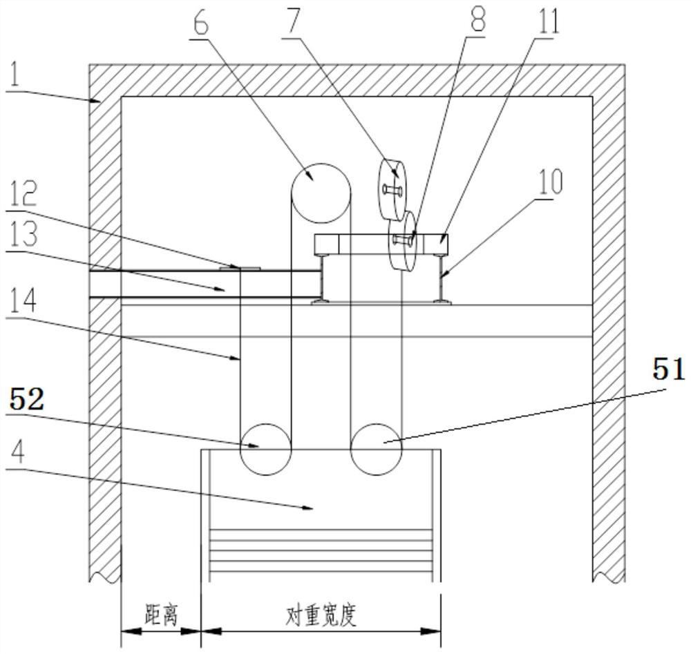
[0037] Such as Figure 4 , Figure 5 and Figure 6 As shown, the counterweight sideslip elevator structure includes a traction machine wheel 7, a machine room guide wheel 8, a traction wire rope 14, a counterweight 4, a first pair of returning sheaves 51, a second pair of returning sheaves 52, a first Counterweight guide wheel 61 and the second counterweight guide wheel 62;

[0038] The traction base 11 is fixed on the load-bearing beam 10 in the hoistway 1;

[0039] The traction wheel 7, the engine room guide wheel 8, the first counterweight guide wheel 61 and the second counterweight guide wheel 62 are fixed in the hoistway;

[0040] The first pair of heavy guide wheels 61 and the second pair of heavy guide wheels 62 are arranged at intervals one after the other;

[0041] The axes of the first pair of heavy guide wheels 61 and the second pair of heavy guide wheels 62 are parallel;

[0042] The machine room guide wheel 8 is located between the first pair of heavy guide w...

Embodiment 2

[0050] Based on the counterweight side-fall elevator structure of Embodiment 1, the traction machine wheel 7 is located between the first counterweight guide wheel 61 and the second counterweight guide wheel 62 in the front and rear direction (well way, car depth direction), and the traction The axis of machine wheel 7 is parallel to the axis of machine room guide wheel 8.

[0051] Preferably, the position of the traction wheel 7 is higher than that of the machine room guide wheel 8 .

[0052] Preferably, the traction machine wheel 7 is located directly above the machine room guide wheel 8 .

[0053] Preferably, the traction sheave 7 is arranged on the side near the car of the machine room guide wheel 8 .

[0054] In the counterweight side-fall elevator structure of Embodiment 2, the traction machine wheel 7 and the machine room guide wheel 8 can be placed horizontally or vertically.

Embodiment 3

[0056] Based on the counterweight side-fall elevator structure of Embodiment 1, the traction machine wheel 7, the machine room guide wheel 8 and the traction machine are all fixed on the traction frame 11;

[0057] The first counterweight guide wheel (61) and the second counterweight guide wheel (62) are fixed on the hoistway wall or are fixed on the load-bearing beam (10) by a bracket.

[0058] Preferably, the traction wire rope 14 is suspended upward from the rope groove at the front side of the second pair of return sheaves 52 to the counterweight rope end plate 12 on the counterweight rope head bearing beam 13 .

[0059] Preferably, the distance between the first pair of heavy guide wheels 61 and the second pair of heavy guide wheels 62 is 1.1 to 1.5 times the thickness of the machine room guide wheels 8;

[0060] The far away car side rope groove of machine room guide wheel 8 penetrates between the first pair of heavy guide wheels 61 and the second pair of heavy guide whe...


PUM


Abstract

The invention discloses a counterweight side-falling elevator structure. The structure is characterized in that a traction steel wire rope enters a first counterweight rope return wheel arranged at the top end of the rear part of a counterweight through a traction machine wheel and a machine room guide wheel, enters a first counterweight guide wheel after being guided by the first counterweight rope return wheel and is horizontally and forwards transmitted into a second counterweight guide wheel, and the second counterweight guide wheel is used for ensuring that the traction steel wire rope vertically falls into a second counterweight rope return wheel arranged at the top end of the front part of the counterweight and is finally suspended to a counterweight rope head bearing beam. According to the arrangement mode, the traction steel wire rope enters the two counterweight rope return wheels arranged at the upper end of the counterweight from the adjacent side, the counterweight can move backwards by a distance equal to the diameter of the counterweight rope return wheel, so that the counterweight is placed in the middle in the front-back direction as much as possible, the counterweight is far away from a car door plate assembly located on the front side of an elevator car as much as possible, the safety space between the counterweight and a hoistway, the elevator car and the car door plate assembly is guaranteed, and even if the traction machine wheel and the machine room guide wheel are not placed obliquely, the distance between the counterweight and the car door plate assembly can be larger than the safety distance.

Description

technical field [0001] The invention relates to elevator technology, in particular to a counterweight side-drop elevator structure. Background technique [0002] The emergence of elevators greatly facilitates people to ride and transport goods, reduces manpower and improves people's work efficiency. In order to balance the load and the weight of the car, the elevator needs to be equipped with a counterweight system to reduce the load of the elevator traction system. Load, improve safety. At present, the large-load elevators used in the market are generally 2 tons, 3 tons, and 5 tons. Due to the large load, the supporting counterweight device is more than twice that of ordinary passenger elevators, but the left-right width and front-to-back depth of the shaft are Therefore, when the front and rear depths of the hoistway are insufficient, it is difficult to arrange the counterweight, which is also a problem that has plagued large-duty elevators for a long time. [0003] The ...

Claims


Application Information

Patent Timeline
IPC IPC(8): B66B11/04B66B17/12B66B13/30B66B11/00
CPCB66B11/0065B66B11/04B66B13/303B66B17/12
Inventor 宋祥爱杨克雷刘世丹李硕王孝宁
Owner YUNGTAY ELEVATOR EQUIP CHINA
Why Eureka
Try Eureka