A smart grid substation system transformer installation auxiliary device

An installation assistance and smart grid technology, applied in safety devices, lifting devices, transportation and packaging, etc., can solve problems such as low degree of automation, bruising of transformer installers, low efficiency of transformers, etc., to increase and reduce potential safety hazards Effect

Active Publication Date: 2022-04-26
ECONOMIC TECH RES INST OF STATE GRID ANHUI ELECTRIC POWER +1
View PDF0 Cites 0 Cited by
  • Summary
  • Abstract
  • Description
  • Claims
  • Application Information

AI Technical Summary

Problems solved by technology

[0004] 1. When the transformer is hoisted by a crane and moved to the area to be installed, the transformer installer needs to receive and place the transformer. However, during this process, the transformer installer is easily injured by the transformer or collided by the transformer, which makes the transformer Installers have safety hazards in the process of receiving and placing the transformer; and when hoisting construction is carried out in buildings or places with many people, the transformer is likely to collide with other buildings and people during the hoisting process, thus increasing the transformer’s safety. Potential safety hazards during hoisting;
[0005] 2. However, when the transformer is installed at a relatively low position when some cranes cannot enter the site, usually only multiple people can assist in manually lifting the transformer to install the transformer. The low degree of automation leads to the low efficiency of artificially moving and installing the transformer, and the work intensity of the construction personnel in the process of artificially lifting the transformer is high, and there is a hidden danger of being hit by the transformer and breaking the transformer

Method used


Image

  • A smart grid substation system transformer installation auxiliary device
  • A smart grid substation system transformer installation auxiliary device
  • A smart grid substation system transformer installation auxiliary device

Examples


Embodiment Construction

[0038] In order to make the technical means, creative features, goals and effects achieved by the present invention easy to understand, the present invention will be further described below in conjunction with specific illustrations. It should be noted that, in the case of no conflict, the embodiments in the present application and the features in the embodiments can be combined with each other.

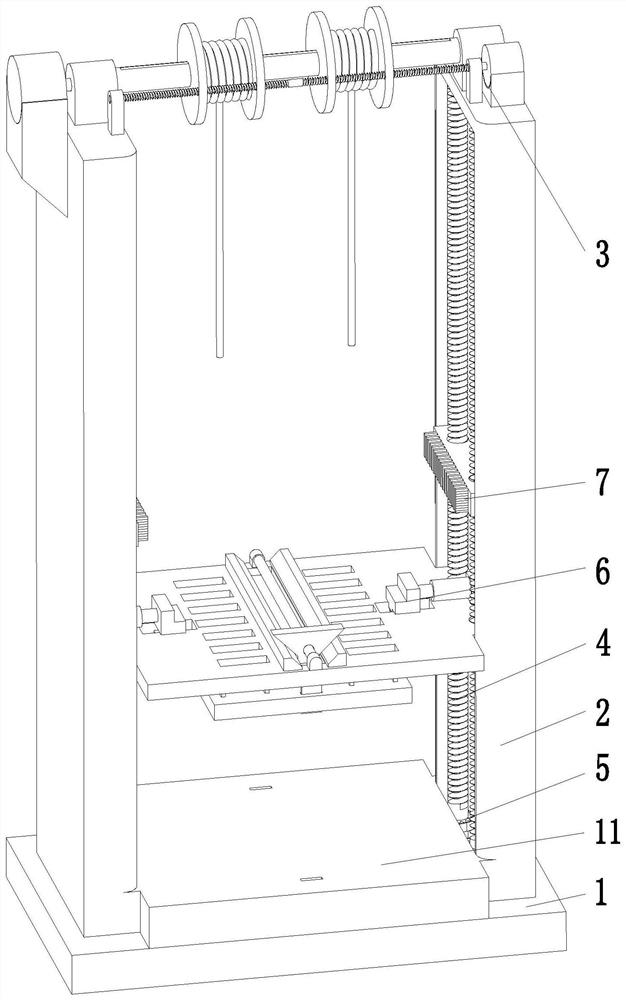
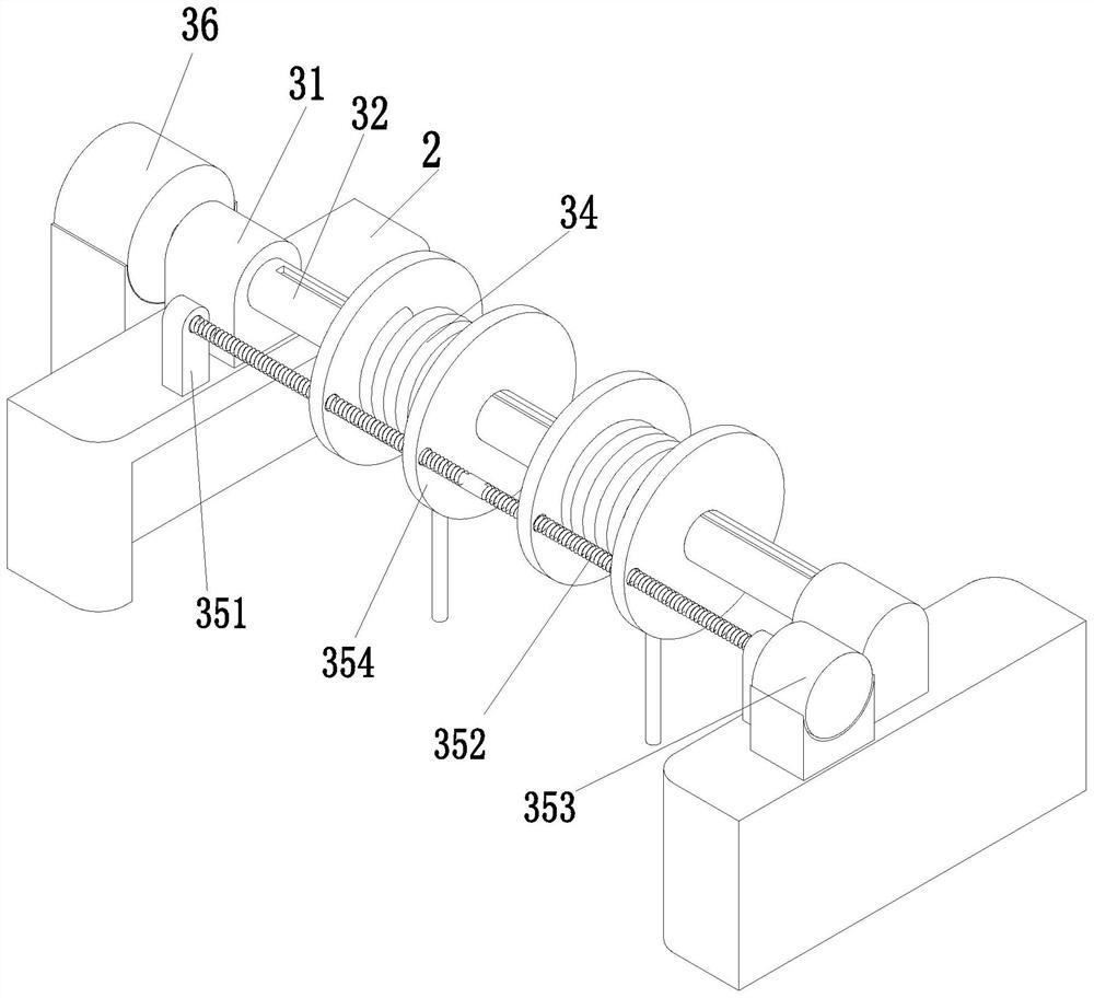
[0039] Such as Figure 1 to Figure 10 As shown, in order to solve the above problems, the present invention provides an auxiliary device for installing a transformer in a smart grid substation system, including a base 1, a supporting side plate 2, a traction mechanism 3, a lifting screw 4, a driving mechanism 5, The transport mechanism 6 and the limit mechanism 7, the support side plates 2 are symmetrically installed on the left and right sides on the upper end surface of the base 1, and the traction mechanism 3 is installed on the top of the support side plate 2, and the upper end s...


PUM


Abstract

The invention relates to an auxiliary device for transformer installation in a smart grid substation system, comprising a base, a supporting side plate, a traction mechanism, a lifting screw, a driving mechanism, a transport mechanism and a limit mechanism, and supports are symmetrically installed on the left and right sides of the upper end surface of the base The side plate, the top of the support side plate is equipped with a traction mechanism, the upper end of the base is located on the inner side of the support side plate, and the lifting screw is installed symmetrically front and back, and the lower end of the lifting screw is equipped with a driving mechanism. The transportation mechanism and the limit mechanism are installed in sequence on the top; the existing technology exists when the transformer is installed by hoisting and artificial installation: the transformer is easy to collide with other buildings and personnel during the hoisting process, making it easy for personnel to The transformer is bumped, collided and dropped, and the transformer is damaged by collision; the efficiency of artificially moving and installing the transformer is low, and the work intensity of the personnel who lifts the transformer is relatively high.

Description

technical field [0001] The invention relates to the field of grid erection, in particular to an auxiliary device for transformer installation in a smart grid substation system. Background technique [0002] A transformer is a static electrical device used to convert AC voltage and current to transmit AC power. It realizes electric energy transmission based on the principle of electromagnetic induction; transformers can be divided into power transformers, test transformers, instrument transformers and special-purpose transformers in terms of their uses: among them, power transformers are necessary equipment for power transmission and distribution, and power distribution for power users. The role of the transformer is multifaceted. It can not only increase the voltage to send electric energy to the power consumption area, but also reduce the voltage to the voltage used at all levels to meet the needs of power consumption. In short, both step-up and step-down must be done by t...

Claims


Application Information

Patent Timeline
Patent Type & Authority Patents(China)
IPC IPC(8): B66C25/00B66C13/06B66C15/00B66F7/00B66F7/28
CPCB66C25/00B66C13/06B66C15/00B66F7/025B66F7/28
Inventor 葛成朱刘柱王绪利周跃吴晓鸣杨欣张理孟晓星
Owner ECONOMIC TECH RES INST OF STATE GRID ANHUI ELECTRIC POWER
Why Eureka
Try Eureka