
Beer distributor

A dispenser and beer technology, applied in liquid distribution, distribution devices, packaging, etc., can solve the problems of easy breeding of bacteria and unhygienic, and achieve the effects of avoiding breeding of bacteria, convenient disassembly and ensuring stability

Pending Publication Date: 2020-12-29
TALOS TECH CORP
View PDF1 Cites 1 Cited by
  • Summary
  • Abstract
  • Description
  • Claims
  • Application Information

AI Technical Summary

Problems solved by technology

[0005] The purpose of the present invention is to address the above problems in the prior art, and propose a beer dispenser, which solves the problems of being unhygienic and easy to breed bacteria after long-term use

Method used


Image

  • Beer distributor
  • Beer distributor
  • Beer distributor

Examples


Embodiment 1

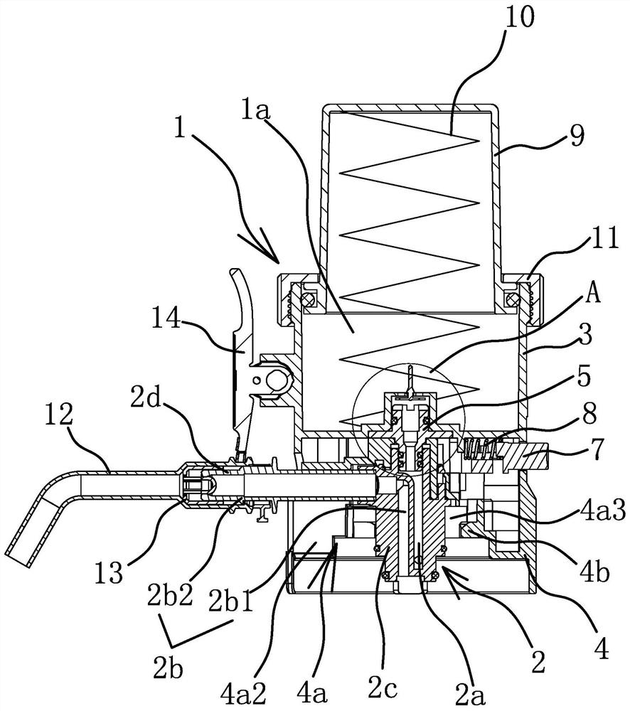
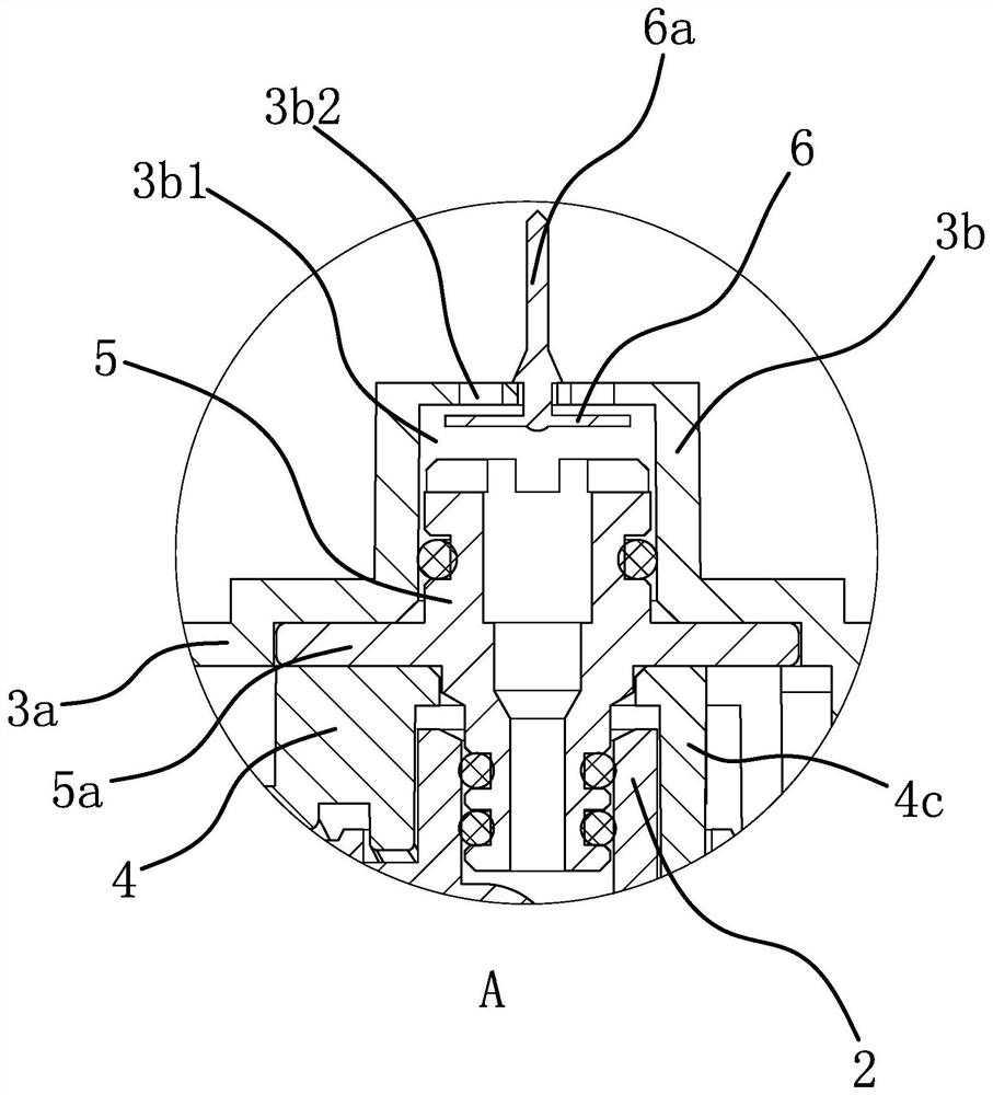
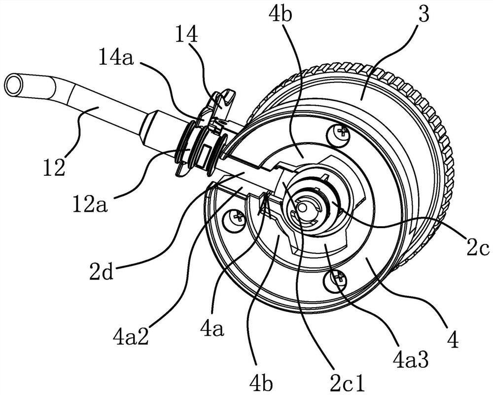
[0041] Such as figure 1 and figure 2 As shown, the beer dispenser includes a cylindrical body 1, the upper part of the body 1 is provided with a pressurized chamber 1a that can realize pressurization through volume change, and the bottom of the body 1 is connected with a core assembly 2. The core assembly 2 is provided with an air intake channel 2a and a wine outlet channel 2b, and the bottom of the body 1 is provided with an installation cavity 4a for the core assembly 2 to be inserted into the body 1, and the core assembly 2 is inserted into the installation cavity 4a so that the air intake channel 2a The inlet is connected with the pressurized chamber 1a, the installation chamber 4a runs through the side of the body 1, the outlet of the wine outlet channel 2b is located at the side of the core assembly 2 and extends out of the side of the body 1 through the installation chamber 4a. Among them, the core assembly 2 includes a main body 2c and a tubular wine outlet part 2d a...

Embodiment 2

[0049] The structure and principle of this embodiment are basically the same as that of Embodiment 1. The difference is that in this embodiment, the inner hole of the extension pipe 12 includes a hole 1 and a hole 2 arranged on the same center line, and the diameter of the hole 2 is larger than that of the hole 1. The outer end of the wine outlet 2d is pierced in the second hole, and the plug 13 is connected with the outer end of the wine outlet 2d through several branches. When the extension tube 12 slides, the plug 13 can be blocked in the first hole or retract into hole two.

Embodiment 3

[0051] The structure and principle of this embodiment are basically the same as that of Embodiment 1, the difference is that in this embodiment, the body 1 is provided with a U-shaped pin inserted from the side, and the clamping structure includes a symmetrical arrangement on the core assembly 2. The slot on the outside of the main body 2c and the two rods of the U-shaped slot, and the two rods of the U-shaped bolt are inserted into the two slots.


PUM


Abstract

The invention provides a beer distributor, and belongs to the technical field of drinking equipment. The problems that an existing beer distributor is not sanitary after being used for a long time, and bacteria are prone to breeding are solved. The beer distributor comprises a cylindrical body, wherein a pressurizing cavity capable of achieving pressurization through a volume change is formed in the upper part of the body; a core assembly is connected to the bottom of the body, the core assembly is of an integrated structure or is fixedly connected into a whole, and an air inlet channel and abeer outlet channel are formed in the core assembly; a mounting cavity allowing the core assembly to be inserted into the body is formed in the bottom of the body; the core assembly is inserted into the mounting cavity to enable an inlet of the air inlet channel to communicate with the pressurizing cavity, and the core assembly and the body are positioned through a clamping structure in the axialdirection; the mounting cavity penetrates through the side part of the body; and an outlet of the wine outlet channel is formed in the side part of the core assembly and extends out of the side part of the body through the mounting cavity. The beer distributor has the advantages of being capable of keeping sanitary, avoiding bacterium breeding and being low in cost.

Description

technical field [0001] The invention belongs to the technical field of drinking equipment and relates to a beer dispenser. Background technique [0002] With the continuous improvement of people's living standards, beer has become an indispensable drink in people's daily leisure activities or business activities. At the same time, people have higher requirements for the way of drinking beer, and more and more people prefer to drink beer. Hygienic, fresh and delicious draft beer. Draft beer on the market is packed in barrels, and then special machines or devices are used to distribute the liquor, but the traditional distribution machines or devices are very bulky and are basically only used in fixed places such as bars and restaurants. Portable use, especially outdoors, is not possible. [0003] For this reason, Chinese patent once disclosed the beer keg air pressure valve that application number is 93231183.0, and it is made of air pressure mechanism and wine outlet mechan...

Claims


Application Information

Patent Timeline
Patent Type & Authority Applications(China)
IPC IPC(8): B67D1/06B67D1/08
CPCB67D1/06B67D1/08
Inventor 邱迪清邱迪林
Owner TALOS TECH CORP
Learn More