Assembly type buffering beam falling prevention device

An anti-fall beam and assembled technology, which is applied in the direction of erecting/assembling bridges, bridges, bridge parts, etc., can solve the problems that the anti-fall beam facilities are easily damaged and difficult to replace, and achieve the effect of simple maintenance and replacement

Active Publication Date: 2020-12-29
INST OF ENG MECHANICS CHINA EARTHQUAKE ADMINISTRATION
View PDF9 Cites 4 Cited by
  • Summary
  • Abstract
  • Description
  • Claims
  • Application Information

AI Technical Summary

Problems solved by technology

[0003] The present invention intends to provide an assembled buffer anti-fall beam device to solve the problem that the existing anti-fall beam facilities are easily damaged and difficult to replace after damage

Method used


Image

  • Assembly type buffering beam falling prevention device
  • Assembly type buffering beam falling prevention device
  • Assembly type buffering beam falling prevention device

Examples


Embodiment

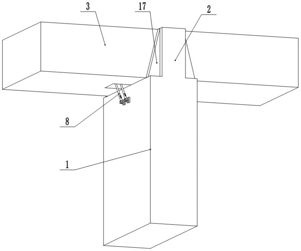
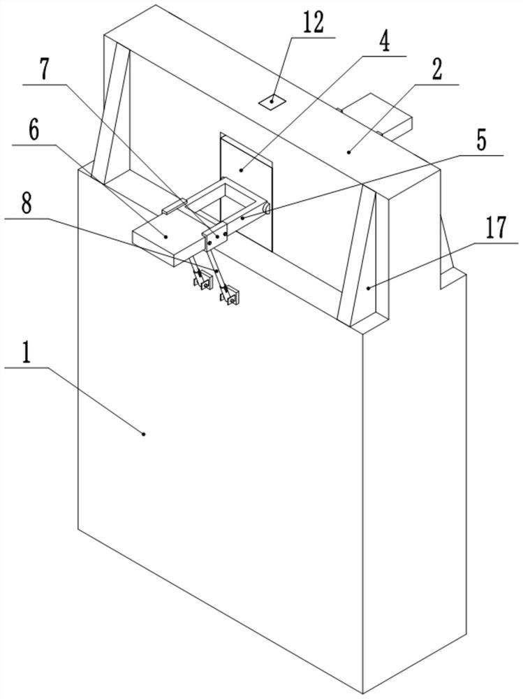
[0024] Such as figure 1 , figure 2 , image 3 , Figure 4 , Figure 5 and Image 6 Shown:

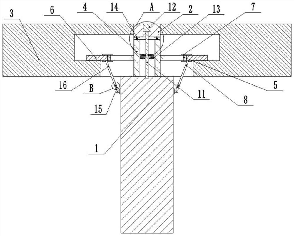
[0025] An assembled buffer anti-fall beam device, comprising a bridge pier 1, a vertically arranged anti-collision plate is fixed on the top of the bridge pier 1, the anti-collision plate coincides with the center line of the bridge pier 1, and fixed frames 5 are symmetrically arranged on both sides of the anti-collision plate, and fixed The movable end of the frame 5 is hinged with a connecting plate; two beams 3 are symmetrically arranged on the pier 1, and the end faces of the beams 3 are provided with a chamber for accommodating the connecting plate, and the bottom wall of the chamber is provided with an entrance, and the width of the entrance is larger than Width of the connecting plate and the fixed frame 5, the connecting plate is hinged with a connecting rod 8, the connecting rod 8 is a spring telescopic rod, and the movable end of the connecting rod 8 stretches out from t...

specific Embodiment approach

[0026] The positioning block 4 is installed in the cavity, the positioning column 11 is inserted in the concave cavity, and the cover plate 12 is covered to complete the installation of the positioning block 4; the fixing frame 5 and the connecting plate are installed on the side wall of the positioning block 4, Fold the connecting plate and the fixing frame 5; then place the beam body 3 on the pier 1.

[0027] Stretch the connecting rod 8 again, put the fixed frame 5 and the connecting plate flat, make the connecting plate stretch into the beam body 3 chamber and be close to the bottom wall of the chamber, and connect the clamping block 7 to the hinge between the connecting plate and the fixed frame 5 place, and use bolts to fix the block 7, detachably hinge the connecting rod 8 and the pier 1; connect the hydraulic damper 9 and the limit block 10 to the side wall of the connecting plate respectively.

[0028] During an earthquake, when the beam body 3 is displaced laterally,...


PUM


Abstract

The invention relates to the field of bridge construction, and particularly discloses an assembly type buffering beam falling prevention device which comprises a pier. A vertically-arranged anti-collision plate is fixed to the top of the pier, the anti-collision plate coincides with the center line of the pier, fixing frames are symmetrically arranged on the two sides of the anti-collision plate,and connecting plates are hinged to the movable ends of the fixing frames. Two sections of beam bodies are symmetrically arranged on the pier, cavities for containing the connecting plates are formedin the end faces of the beam bodies, entrances and exits are formed in the bottom walls in the cavities, the widths of the entrances and exits are larger than those of the connecting plates and the fixing frames, connecting rods are hinged to the connecting plates and are spring telescopic rods, and the movable ends of the connecting rods extend out of the entrances and exits to be detachably connected to the pier. A plurality of hydraulic dampers are horizontally hinged to the inner walls of the two sides of the cavities, and the other ends of hydraulic dampers are detachably hinged to the connecting plates. Limiting blocks are connected to the two side walls of the connecting plates through bolts, and gaps are reserved between the limiting blocks and the inner side walls of the cavities.The problems that an existing beam falling prevention facility is prone to damage and is not easy to replace after being damaged are solved.

Description

technical field [0001] The invention relates to the technical field of bridge construction, and specifically discloses an assembled buffer and anti-drop beam device. Background technique [0002] my country is one of the countries with the strongest seismic activity and the most severe earthquake disasters in the world, especially in the three seismically active regions of North China, Northwest China, and Southwest China, where there have been instances of falling beams caused by earthquakes. Beam falling is one of the bridge earthquake disasters with the highest frequency, the most destructiveness and the most difficult repair. The damage forms of the earthquake to the bridge superstructure include falling beam damage, collision damage, and support deviating from its guide groove or bottom basin, resulting in loss of horizontal bearing capacity. The main structural measures of the traditional anti-falling beam method are to set concrete blocks, anchor bolts or steel brack...

Claims


Application Information

Patent Timeline
Patent Type & Authority Applications(China)
IPC IPC(8): E01D19/00E01D22/00F16F15/067
CPCE01D19/00E01D22/00F16F15/067
Inventor 孙得璋何先龙戴君武张昊宇李思汉
Owner INST OF ENG MECHANICS CHINA EARTHQUAKE ADMINISTRATION
Why Eureka
Try Eureka