
Cast-in-situ bored pile structure and construction method thereof

A technology of bored piles and steel casings, which is used in infrastructure engineering, sheet pile walls, buildings, etc., can solve the problems of casing shaking, casing deviation, affecting the overall shape of the cast-in-place piles, and reducing manual operations. , reduce the effect of shaking

Active Publication Date: 2020-12-29
安徽淠源水利工程有限公司
View PDF10 Cites 2 Cited by
  • Summary
  • Abstract
  • Description
  • Claims
  • Application Information

AI Technical Summary

Problems solved by technology

During the concrete pouring process, the casing will shake, and when the shaking is severe, the casing will be shifted and tilted, which will affect the overall shape of the cast-in-place pile after pouring
[0004] In view of the above-mentioned related technologies, the inventor believes that during the concrete pouring process, the casing will shake, and when the shaking is severe, the casing will shift and tilt, which will affect the overall shape of the cast-in-place pile after pouring

Method used


Image

  • Cast-in-situ bored pile structure and construction method thereof
  • Cast-in-situ bored pile structure and construction method thereof
  • Cast-in-situ bored pile structure and construction method thereof

Examples


Embodiment 1

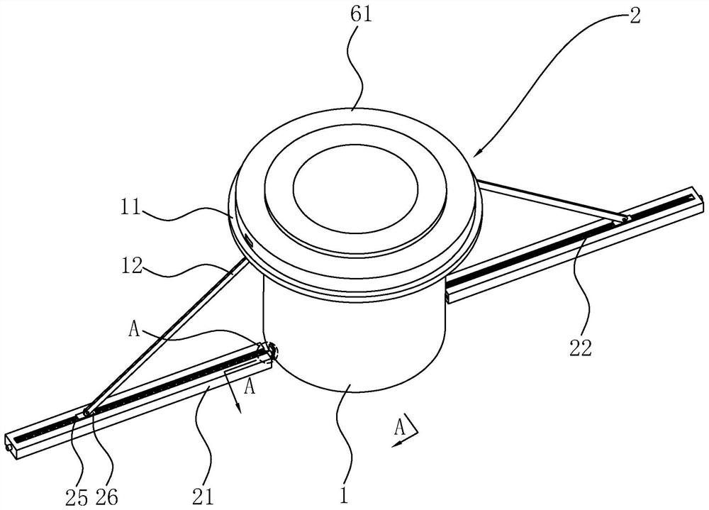
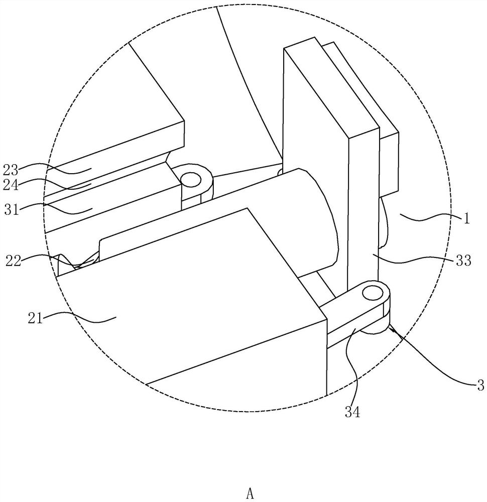
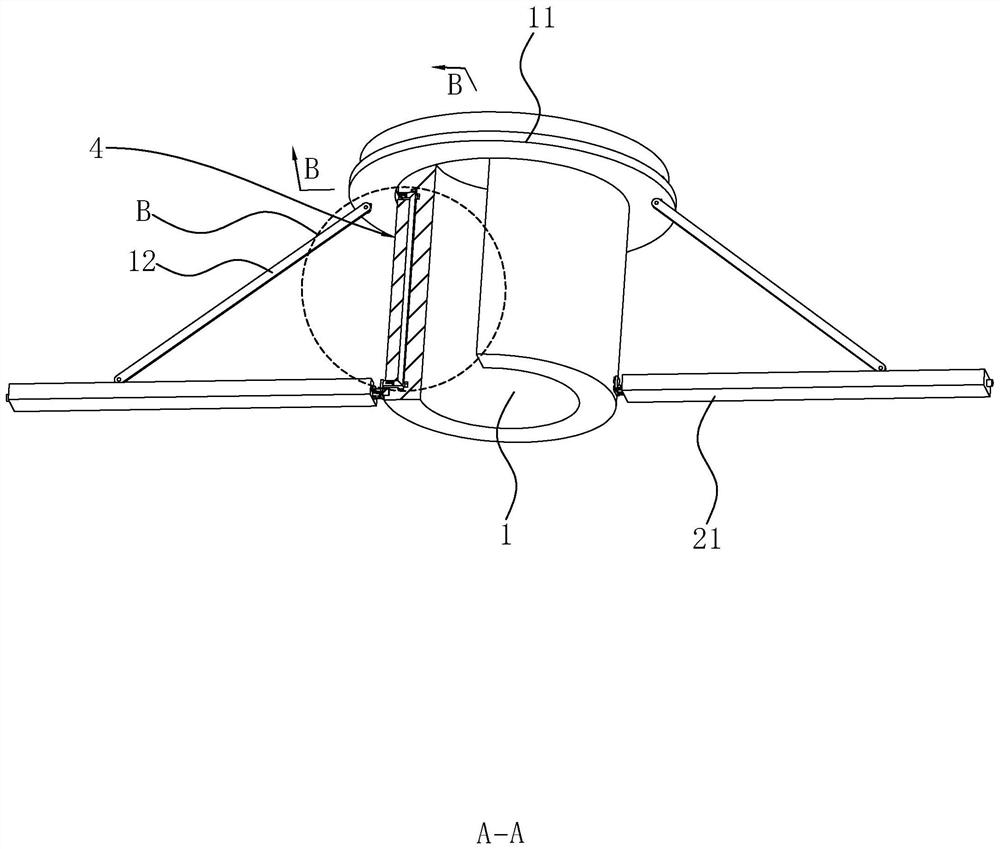
[0043] refer to figure 1 with figure 2A bored pile structure includes a steel casing, a support ring 11 vertically slidably arranged on the outer peripheral surface of the steel casing 1, and two struts 12 hinged to the bottom surface of the support ring 11 respectively. A fixing ring 61 is fixed on the top of the steel casing 1 , and two sets of connection assemblies 6 for fixedly connecting the supporting ring 11 and the fixing ring 61 are arranged between the supporting ring 11 and the fixing ring 61 . Both sides of the steel casing 1 are respectively provided with driving mechanisms 2 for driving the support ring 11 to move upward. Each group of driving mechanisms 2 includes a guide rail 21 arranged on one side of the steel casing 1 and a lead screw 22 penetrating in the guide rail 21 and rotatably connected to the end of the guide rail 21 away from the steel casing 1 . The top of the guide rail 21 is provided with a guide rail groove 23 , and the two sides of the guide...

Embodiment 2

[0056] A construction method for bored piles, comprising the steps of:

[0057] S1. Clean up the ground and compact the position where the cast-in-situ pile needs to be formed;

[0058] S2. Drill a hole with a depth of 3m and bury the steel casing 1. Before the steel casing 1 is buried, set the support ring 11 on the side of the steel casing 1. The inner diameter of the steel casing 1 is selected to be 30cm larger than the pile diameter;

[0059] S3. Laying guide rails 21 on both sides of the steel casing 1, rotating the guide rails 21, so that the support ring 11 rises to contact with the fixed ring 61, and the support ring 11 and the fixed ring 61 are fixedly connected by the connection assembly 6;

[0060] S4. Install a reinforcement cage in the steel casing 1, pour concrete after installation, and take out the steel casing 1 after the concrete has solidified.

Embodiment 3

[0062] A construction method for bored piles, comprising the steps of:

[0063] S1. Clean up the ground and compact the position where the cast-in-situ pile needs to be formed;

[0064] S2. Drill a hole with a depth of 2m and bury the steel casing 1. Before the steel casing 1 is buried, set the support ring 11 on the side of the steel casing 1. The inner diameter of the steel casing 1 is selected to be 20cm larger than the pile diameter;

[0065] S3. Laying guide rails 21 on both sides of the steel casing 1, rotating the guide rails 21, so that the support ring 11 rises to contact with the fixed ring 61, and the support ring 11 and the fixed ring 61 are fixedly connected by the connection assembly 6;

[0066] S4. Install a reinforcement cage in the steel casing 1, pour concrete after installation, and take out the steel casing 1 after the concrete has solidified.


PUM


Abstract

The invention relates to a cast-in-situ bored pile structure and a construction method thereof. The cast-in-situ bored pile structure comprises a steel casing, a supporting ring and two supporting rods. A fixing ring is fixed to the top of the steel casing, and a connecting assembly is arranged between the supporting ring and the fixing ring. Driving mechanisms are arranged at the two sides of thesteel casing respectively. A preparation method of the cast-in-situ bored pile structure comprises the steps that the ground is cleaned, and the position where a cast-in-situ bored pile needs to be formed is tamped; drilling is carried out, and the steel casing is embedded, wherein the peripheral side of the steel casing is sleeved with the supporting ring before the steel casing is embedded; guide rails are laid at the two sides of the steel casing correspondingly, a lead screw is rotated so that the supporting ring ascends to make contact with the fixing ring, and the supporting ring and the fixing ring are fixedly connected through the connecting assembly; and a reinforcement cage is installed in the steel casing, concrete is poured after installation is completed, and the steel casingis taken out after the concrete is condensed. By means of the cast-in-situ bored pile structure and the method, the influence of concrete pouring on the overall shape of the cast-in-place pile can bereduced.

Description

technical field [0001] The present application relates to the field of cast-in-situ piles, in particular to a bored cast-in-place pile structure and a construction method thereof. Background technique [0002] At present, the cast-in-place pile refers to a pile formed by forming a pile hole in the foundation soil by means of mechanical drilling, steel pipe extrusion or manual excavation on the project site, and pouring concrete into it. [0003] Related technologies can refer to the Chinese invention patent application with publication number CN102808411A, which discloses a bored pile casing and its use method, including a cylindrical casing, and two lifting lugs are relatively fixed on the outer peripheral surface of the casing. The outer wall of the tube is provided with cutting slits along the radial direction of the casing, and the top and bottom ends of the cutting slits are respectively provided with buckles. During the concrete pouring process, the casing will shake,...

Claims


Application Information

Patent Timeline
Patent Type & Authority Applications(China)
IPC IPC(8): E02D5/68E02D13/02E02D5/36
CPCE02D5/68E02D13/02E02D5/36
Inventor 丁配玲马俊学施俊黄燕
Owner 安徽淠源水利工程有限公司
Learn More