Pump body assembly, compressor and air conditioner

A component and pump body technology, which is applied in the field of compressors, can solve problems such as increased wear of the crankshaft and main bearings, affecting the service life of the compressor, and insufficient oil supply to the main shaft of the crankshaft, so as to achieve sufficient oil supply, improve service life, and avoid pump damage. body stuck effect

Active Publication Date: 2020-12-29
ANHUI MEIZHI PRECISION MFG
View PDF8 Cites 2 Cited by
  • Summary
  • Abstract
  • Description
  • Claims
  • Application Information

AI Technical Summary

Problems solved by technology

The size and position design of the oil guide groove are important factors affecting the lubrication of the crankshaft. If the design is improper, the oil supply to the main shaft of the crankshaft will be insufficient when the compressor is running, resulting in increased wear of the crankshaft and main bearing. Fracture and other problems, thus affecting the service life of the compressor

Method used


Image

  • Pump body assembly, compressor and air conditioner
  • Pump body assembly, compressor and air conditioner
  • Pump body assembly, compressor and air conditioner

Examples


Embodiment Construction

[0059] In order to understand the above-mentioned purpose, features and advantages of the present invention more clearly, the present invention will be further described in detail below in conjunction with the accompanying drawings and specific embodiments. It should be noted that, in the case of no conflict, the embodiments of the present application and the features in the embodiments can be combined with each other.

[0060] In the following description, many specific details are set forth in order to fully understand the present invention. However, the present invention can also be implemented in other ways different from those described here. Therefore, the protection scope of the present invention is not limited by the specific details disclosed below. EXAMPLE LIMITATIONS.

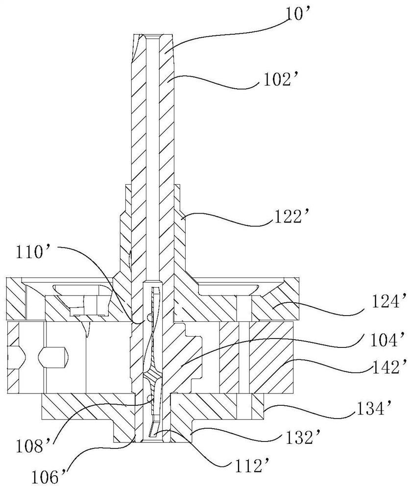
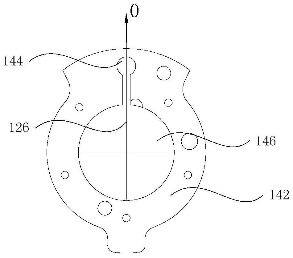
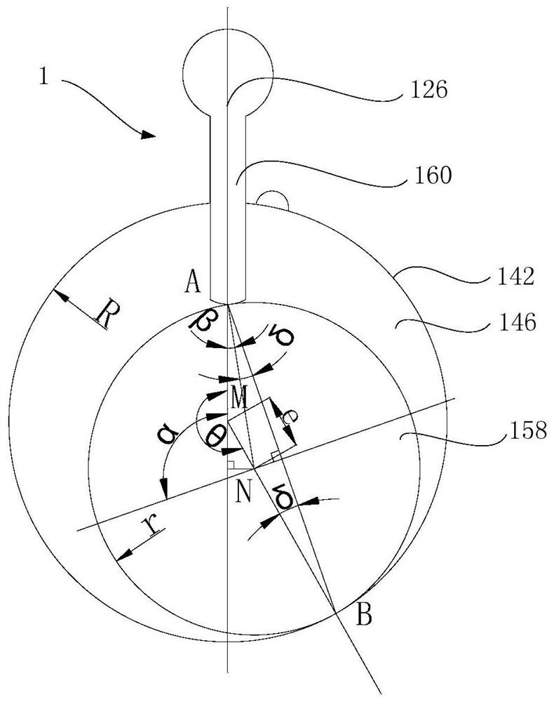
[0061] Refer below Figure 2 to Figure 13 The pump body assembly 1, compressor and air conditioner according to some embodiments of the present invention are described.

[0062] According to one em...


PUM


Abstract

The invention provides a pump body assembly, a compressor and an air conditioner. The pump body assembly comprises a crankshaft, main bearings and cylinder bodies; the crankshaft comprises a main shaft part and an eccentric part, and the distance between the center line of the main shaft part and the center line of the eccentric part is e; the main bearings comprise hub parts, the main shaft partpenetrates through through holes of the hub parts, and first oil guide grooves are formed in the hole walls of the through holes; the cylinder bodies are provided with sliding sheet grooves and centerholes, the crankshaft is arranged in the center holes in a penetrating mode, the main bearings are located on the two sides of the cylinder bodies, the radius of the center hole is R, and the difference value between R and e is r; and the value range of an included angle formed by a first connecting line between the center of the center hole and the center of the sliding sheet groove in the sameprojection plane and a second connecting line between the termination point of the first oil guide groove at the end, away from the eccentric part, of the hub part and the center of the through hole is as follows: see the specification for the symbol. According to the pump body assembly, oil films at all positions, in contact with the main bearings, of the crankshaft are uniform, the abnormal abrasion problem of the crankshaft main shaft part is effectively solved, and the service life of the compressor is prolonged.

Description

technical field [0001] The invention relates to the technical field of compressors, in particular to a pump body assembly, a compressor and an air conditioner. Background technique [0002] At present, the crankshaft lubrication of the pump body of the compressor in the related art is generally oil supply through the helical oiling blade installed in the inner hole of the lower part of the crankshaft countershaft. The lubrication of the main shaft and the auxiliary shaft of the crankshaft is mainly provided by oil guide grooves arranged in the inner holes of the main bearing and the auxiliary bearing. The size and position design of the oil guide groove are important factors affecting the lubrication of the crankshaft. If the design is improper, the oil supply to the main shaft of the crankshaft will be insufficient when the compressor is running, resulting in increased wear of the crankshaft and main bearing. Fracture and other problems, thus affecting the service life of ...

Claims


Application Information

Patent Timeline
Patent Type & Authority Applications(China)
IPC IPC(8): F04C18/356F04C29/02
CPCF04C18/3566F04C29/02F04C18/356F04C2240/56F04C29/028F04C2240/601F04B39/0094F04C18/04F04C29/023F04C18/3564F04C18/322F04C2230/603F04C18/3562F04C15/0088F04C18/32F04C18/324F04C2/02F04C18/02
Inventor 郑礼成李进
Owner ANHUI MEIZHI PRECISION MFG
Why Eureka
Try Eureka