
Intelligent switch testing device and method

A technology of intelligent switch and testing device, which is applied in the direction of measuring device casing and circuit breaker testing, etc., which can solve the problems of safety incidents, uneven mastery of safe electricity knowledge, and damage, so as to improve testing efficiency and eliminate electricity safety incidents , Ease of maintenance and replacement

Pending Publication Date: 2020-12-29
北京如影智能科技有限公司
View PDF4 Cites 4 Cited by
  • Summary
  • Abstract
  • Description
  • Claims
  • Application Information

AI Technical Summary

Problems solved by technology

Usually, smart switches are tested with 220V alternating current, and the testers use connecting wires to directly connect the AC power supply and the smart switch for testing, which poses a great challenge to the safety of the test, and because the personnel involved in the test or test Including operators, software engineers, hardware engineers, etc., the people involved in related work are more complicated, and the knowledge of safe electricity use is also uneven. When the single live wire is connected, there may even be reversed connections, which can easily lead to electricity safety incidents.
At present, on the basis of wiring, insulating tape is used to wrap the exposed wire ends and terminals. However, as the test time increases, the insulating tape will fall off and be damaged due to the decrease in viscosity, which cannot completely prevent the occurrence of electrical safety incidents.

Method used

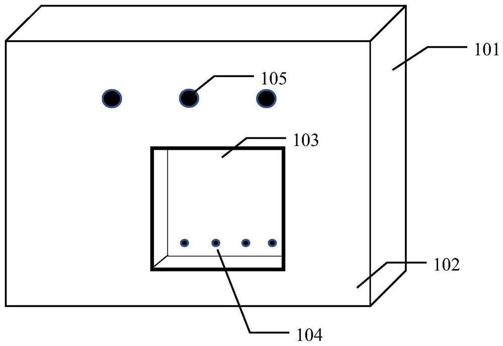
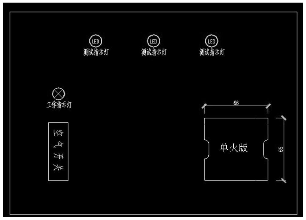
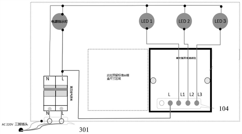

Image

  • Intelligent switch testing device and method
  • Intelligent switch testing device and method
  • Intelligent switch testing device and method

Examples


Embodiment Construction

[0038] In order to enable those skilled in the art to better understand the solutions of the present invention, the technical solutions in the embodiments of the present invention will be clearly and completely described below in conjunction with the drawings in the embodiments of the present invention.

[0039] In some processes described in the specification and claims of the present invention and the above-mentioned drawings, a plurality of operations appearing in a specific order are contained, but it should be clearly understood that these operations may not be performed in the order in which they appear herein Execution or parallel execution, the serial numbers of the operations, such as 101, 102, etc., are only used to distinguish different operations, and the serial numbers themselves do not represent any execution order. Additionally, these processes can include more or fewer operations, and these operations can be performed sequentially or in parallel. It should be n...


PUM


Abstract

The invention discloses an intelligent switch testing device and method. The intelligent switch testing device and method can improve the safety of testing operation and optimize the testing efficiency. The intelligent switch testing device comprises a case and a panel covering one side of the case. The panel comprises at least one test position for accommodating an intelligent switch. A probe isarranged in each test position, and the probe comprises a power supply probe corresponding to a power supply wiring end of the intelligent switch and an on-off key probe corresponding to an on-off keywiring end of the intelligent switch. A circuit module is arranged in the case. Each power supply probe is connected with an external power supply through the circuit module, and each on-off key probe is connected with the external power supply through the circuit module after the on-off key probe is in series connection with a state indicating lamp. Therefore the intelligent switch is powered onwhen placed in the test position, the state indicating lamp is lightened or extinguished according to the state of the on-off key of the intelligent switch, and the state indicating lamp is displayedon the panel.

Description

technical field [0001] The present invention relates to the technical field of smart switches, and more particularly, to a smart switch testing device and method. Background technique [0002] Intelligent switch refers to the unit that uses the combination and programming of the control board and electronic components to realize the circuit intelligent switch control. Faced with many rounds of testing and debugging during the R&D and production phases. Usually, smart switches are tested with 220V alternating current, and the testers use connecting wires to directly connect the AC power supply and the smart switch for testing, which poses a great challenge to the safety of the test, and because the personnel involved in the test or test Including operators, software engineers, hardware engineers, etc., the people involved in related work are relatively complex, and their knowledge of safe electricity use is also mixed. When the single live wire is connected, there may even b...

Claims


Application Information

Patent Timeline
Patent Type & Authority Applications(China)
IPC IPC(8): G01R31/327G01R1/04
CPCG01R31/327G01R1/04
Inventor 周大勇李玉怀张永磊张乐陈彪
Owner 北京如影智能科技有限公司
Learn More