
A baking device for the production of flame-retardant braided sleeves for cables

A baking device and cable technology, which is applied in the direction of measuring devices, cable/conductor manufacturing, circuits, etc., can solve the problems of high work intensity and low work efficiency, and achieve the effects of improving baking accuracy, preventing burns, and improving detection accuracy

Active Publication Date: 2022-05-10
衡阳凌云特种材料有限公司
View PDF15 Cites 1 Cited by
  • Summary
  • Abstract
  • Description
  • Claims
  • Application Information

AI Technical Summary

Problems solved by technology

[0002] Cables used in installation environments with heat sources generally have a flame-retardant braided sleeve on their surface to improve the flame-retardant performance of the cable. Since the flame-retardant braided sleeve is directly in contact with the heat source, the flame-retardant and high-temperature resistance performance is directly related to Depending on the product quality of the flame-retardant braided sleeve, during the processing of the flame-retardant braided sleeve, high-temperature resistance testing will be carried out to detect the high-temperature resistance strength of the flame-retardant braided sleeve. The current high-temperature resistance strength operation method is determined by the baking equipment To perform high-temperature testing on the flame-retardant braided casing, but the existing baking equipment can only perform baking inspection on one side of the flame-retardant braided casing, and when testing the other side, it is necessary to change the direction of the flame-retardant braided casing, and then Repeated detection, this method leads to greater work intensity and lower work efficiency

Method used

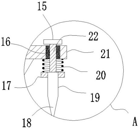

Image

  • A baking device for the production of flame-retardant braided sleeves for cables
  • A baking device for the production of flame-retardant braided sleeves for cables

Examples


Embodiment

[0021] like Figure 1-2 As shown, a baking device for producing flame-retardant braided sleeves for cables, comprising:

[0022] There are two winding rollers, which are respectively defined as the first winding roller 3 and the second winding roller 14, wherein the first winding roller 3 is used for winding the flame retardant braid for cables Sleeve 13, the second winding roller 14 is driven by the transmission mechanism to rotate intermittently, so that the flame-retardant braided sleeve 13 for cables is wound on the second winding roller 14;

[0023] A baking assembly, the baking assembly includes a baking chamber 12 disposed between the first winding roller 3 and the second winding roller 14 , and the baking chamber 12 is adjacent to the first winding roller 3 on one side up and down Two infrared heating plates are installed opposite to each other, and the two infrared heating plates are respectively defined as the upper infrared heating plate 4 and the lower infrared he...


PUM


Abstract

The invention discloses a baking device for producing flame-retardant braided sleeves for cables, which includes a first winding roller, a second winding roller, a transmission mechanism, a baking component, and a cleaning component. The baking component includes a baking chamber, Upper infrared heating plate, lower infrared heating plate, through slot. The beneficial effect achieved by the present invention is that the flame-retardant braided sleeve for the cable passes between the two infrared heating plates through the winding of the flame-retardant braided sleeve by the second winding roller, and is passed by the upper infrared heating plate. and the lower heating plate to simultaneously bake the upper and lower sides of the flame-retardant braided casing for cables, which improves the detection efficiency and detection accuracy. Since the transmission mechanism is set to drive the second winding roller to rotate intermittently, the flame-retardant braided cables for cables The casing moves intermittently, so that the flame-retardant braided casing can stop moving for a short time, so that the upper infrared heating plate and the lower infrared heating plate can fully bake the flame-retardant braided casing for cables, and the baking accuracy is improved.

Description

technical field [0001] The invention relates to the field of baking equipment, in particular to a baking device for producing a flame-retardant braided sleeve for cables. Background technique [0002] Cables used in installation environments with heat sources are generally covered with flame-retardant braided sleeves on their surfaces to improve the flame-retardant properties of the cables. Since the flame-retardant braided sleeves are directly in contact with the heat source, the flame-retardant and high-temperature resistance performance is directly related. Depending on the product quality of the flame retardant braided sleeve, the flame retardant braided sleeve will be tested for high temperature resistance during the processing to detect the high temperature resistance strength of the flame retardant braided sleeve. To test the flame retardant braided sleeve at high temperature, but the existing baking equipment can only test one side of the flame retardant braided slee...

Claims


Application Information

Patent Timeline
Patent Type & Authority Patents(China)
IPC IPC(8): H01B13/26H01B13/00G01N25/00
CPCH01B13/2606H01B13/0036G01N25/00
Inventor 赖华卢伟红邓前军
Owner 衡阳凌云特种材料有限公司
Learn More