
Apparatus and method for clamping and picking up silicon wafers stored in wafer cassettes, and silicon wafer transfer equipment

A silicon wafer box and silicon wafer technology, applied in the direction of conveyor objects, transportation and packaging, electrical components, etc., can solve the problem of simultaneous or one-time transmission, four silicon wafers cannot be transmitted at the same time or one-time transmission, equipment 10A work efficiency reduction and other issues

Active Publication Date: 2021-03-05
XIAN ESWIN SILICON WAFER TECH CO LTD
View PDF17 Cites 0 Cited by
  • Summary
  • Abstract
  • Description
  • Claims
  • Application Information

AI Technical Summary

Problems solved by technology

[0005] For example, assuming that the equipment 10A needs to transfer the silicon wafers placed in the first to fifth slots in the wafer cassette from top to bottom: if there are silicon wafers in the five slots, the equipment 10A's set of gripper arms 11A and individual gripper arm 12A can grip wafers at the same time, so as to transfer five wafers out of five slots to the target position at one time; missing in the first or fifth slot In the case of silicon wafers, the clamping arm group 11A of the equipment 10A can clamp the silicon wafers, so that four silicon wafers out of the five slots can be transferred to the target position at one time, and at this time, the individual clamping The arm 12A can be in a standby state; however, in the case of missing silicon wafers in the third slot, the clamping arm set 11A of the device 10A cannot be used to clamp the silicon wafer at first, because there must be a clamping arm set 11A in the clamping arm set 11A. The picking arm cannot pick up the silicon wafer, and the equipment 10A will automatically stop and cannot continue to carry out further transmission operations. , The four silicon wafers placed in the fifth slot are clamped and transported, in other words, figure 1 The conventional equipment 10A shown in can not realize the simultaneous transfer or one-time transfer of these four silicon wafers
It can be understood that in the case of missing silicon wafers in the second or fourth slots, and in the case of missing silicon wafers in two of the five slots, it is necessary to use the separate clamping arm 12A to separate the wafers multiple times. transmission, or in other words, simultaneous or one-time transmission cannot be achieved. Obviously, these situations have led to a reduction in the operating efficiency of equipment 10A

Method used


Image

  • Apparatus and method for clamping and picking up silicon wafers stored in wafer cassettes, and silicon wafer transfer equipment
  • Apparatus and method for clamping and picking up silicon wafers stored in wafer cassettes, and silicon wafer transfer equipment
  • Apparatus and method for clamping and picking up silicon wafers stored in wafer cassettes, and silicon wafer transfer equipment

Examples


Embodiment Construction

[0033] The following will clearly and completely describe the technical solutions in the embodiments of the present invention with reference to the drawings in the embodiments of the present invention.

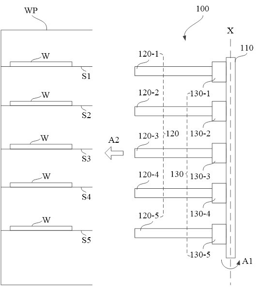
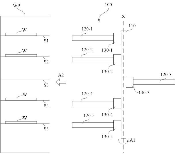
[0034] see figure 2 , an embodiment of the present invention provides a device 100 for clamping a wafer W stored in a wafer cassette WP, wherein, figure 2 It is exemplarily shown that five silicon wafers W are placed in the first to fifth continuous slots S1-S5 of the wafer box WP from top to bottom, and the device 100 may include:

[0035] drive shaft 110, said drive shaft 110 being able to rotate around its own longitudinal axis X, as in figure 2 Schematically shown by arrow A1 in ;

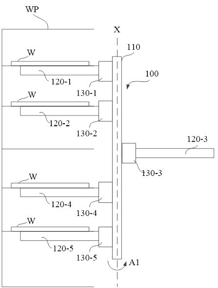
[0036] a plurality of clamping arms 120 arranged on the drive shaft 110, figure 2exemplarily shows the first to fifth gripping arms 120-1 to 120-5 respectively corresponding to the first to fifth slots S1-S5, and the plurality of gripping arms 120 are along the direction perpendicular to...


PUM


Abstract

The embodiment of the present invention discloses a device, method and silicon wafer conveying equipment for clamping and picking up silicon wafers stored in a silicon wafer box. The device may include: a drive shaft capable of rotating around its own longitudinal axis; A plurality of gripping arms on the drive shaft extending in a direction perpendicular to the longitudinal axis of the drive shaft so as to reach into the wafer cassette and hold the wafer as the drive shaft moves close to the cassette. The clips are clamped; the buckle mechanism is arranged between each clamping arm and the drive shaft. The buckle mechanism can be switched between the locked state and the unlocked state. In the locked state, the drive shaft drives the clamping arm so that When the drive shaft rotates, the clamping arm rotates together with the drive shaft. In an unlocked state, the drive shaft cannot drive the clamping arm so that the clamping arm remains stationary when the drive shaft rotates.

Description

technical field [0001] The invention relates to the technical field of semiconductor production, in particular to a device, method and silicon wafer conveying equipment for clamping and picking silicon wafers stored in a silicon wafer box. Background technique [0002] Multi-arm wafer transfer equipment for transferring wafers stored in wafer cassettes is known in the prior art, wherein the wafer cassette typically has a plurality of slots arranged in a stacked manner within the wafer cassette Each slot is suitable for placing a single silicon wafer, while the multi-arm silicon wafer transfer device has a plurality of gripping arms, which can simultaneously or at one time grip the slots corresponding to the plurality of gripping arms The corresponding plurality of silicon wafers, and the plurality of gripping arms can move together with the robot arm of the device to transfer the gripped silicon wafers to the target position. A multi-arm wafer transfer machine can maximize ...

Claims


Application Information

Patent Timeline
Patent Type & Authority Patents(China)
IPC IPC(8): H01L21/677
CPCH01L21/67742H01L21/67766H01L21/67775H01L21/67778
Inventor 吕天爽苏建生
Owner XIAN ESWIN SILICON WAFER TECH CO LTD
Learn More