Microphone plug-in machine

A technology of plug-in machine and microphone head is applied in the direction of electrical components, electrical components, and electrical components to assemble printed circuits, which can solve the problems of inconvenience, complex structure, low work efficiency, etc., and achieve convenient use, high efficiency and simple structure. Effect

Active Publication Date: 2020-12-29
潍坊同达电子科技有限公司
6 Cites 0 Cited by

AI-Extracted Technical Summary

Problems solved by technology

However, the plug-in mechanism of the automatic plug-in machine can only grab one workpiece, and only one workpiece can be inserted into the PCB board at a t...

Method used

In sum, the present invention is by arranging microphone positioning mold conveying mechanism at conveyor belt front end, and microphone positioning mold is delivered on conveyor belt, and vibrating disc feeding mechanism is set at conveyor belt middle section position, and microphone is put into Go to the microphone positioning mold, set the PCB board positioning mold output mechanism at the rear position of the conveyor belt, install the positioned PCB board on the microphone positioning mold, complete the plug-in, and enter the welding process with the transmission of the conveyor belt. The whole process is completed on a transmission belt, which is simple in structure and easy to use. The microphone positioning mold is equipped with several stations, and several PCB boards can be inserted at one time, with high efficiency.
Referring to Fig. 2 and Fig. 3, the conveyer belt 1 is provided with the first separation baffle 11, the distance between the separation baffle 11 is identical with the length of microphone head positioning mold 2, and the width of conveyer belt 1 is the same as that of microphone head Positioning die 2 widths are identical. The microphone positioning die 2 is provided with several microphone stations 21, and the diameter of the microphone stations 21 is the same as the diameter of the microphone, and is used to transport the microphones equidistantly. The microphone positioning die 2 is also provided with positioning protrusions 22 and card position 23, referring to Figure 4, the card position 23 is located at the entrance of the microphone station 21, slightly smal...

Abstract

The invention is suitable for the technical field of plug-in machines, and provides a microphone plug-in machine, which comprises a conveying belt, a microphone positioning die, a microphone positioning die conveying mechanism, a vibration disc feeding mechanism, a PCB positioning die and a PCB positioning die output mechanism. According to the invention, by using the technical scheme, the microphone positioning die conveying mechanism is arranged at the front end of the conveying belt, the microphone positioning die is conveyed to the conveying belt, the vibration disc feeding mechanism is arranged at the middle section of the conveying belt, the microphone is put on the microphone positioning die, the PCB positioning die output mechanism is arranged at the rear section of the conveying belt, the positioned PCB is installed on the microphone positioning die, inserting is completed, and the welding procedure is conducted along with conveying of the conveying belt, so that the whole process is completed on one conveying belt, the structure is simple, use is convenient, the microphone positioning die is provided with a plurality of stations, a plurality of PCBs can be inserted at a time, efficiency is high, and the microphone inserting machine is specially used for assembling microphones and the PCBs.

Application Domain

Printed circuit assemblingElectrical components

Technology Topic

MicrophoneEngineering +1

Image

  • Microphone plug-in machine
  • Microphone plug-in machine
  • Microphone plug-in machine

Examples

  • Experimental program(1)

Example Embodiment

[0029] In order to make the object, technical solution and advantages of the present invention clearer, the present invention will be further described in detail below in conjunction with the accompanying drawings and embodiments. It should be understood that the specific embodiments described here are only used to explain the present invention, not to limit the present invention.
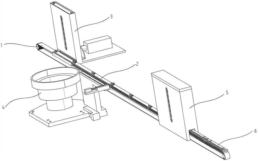
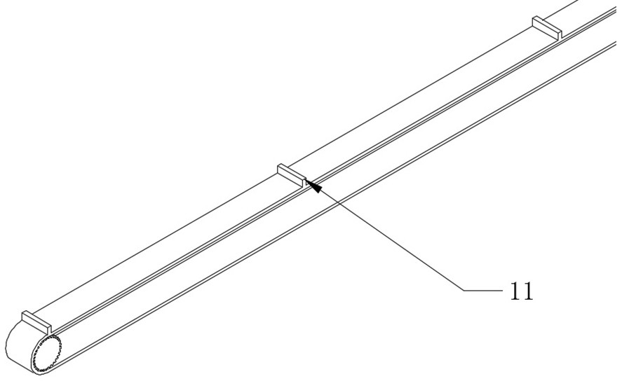
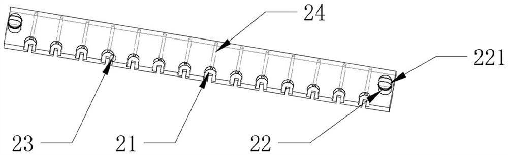
[0030] see figure 1 , The invention provides a microphone plug-in machine. The microphone plug-in machine includes: conveyor belt 1, microphone positioning mold 2, microphone positioning mold output mechanism 3, vibration plate feeding mechanism 4, PCB board positioning mold 6, PCB board positioning mold output mechanism 5, microphone positioning mold The output mechanism 3, the vibrating plate feeding mechanism 4, and the PCB board positioning mold output mechanism 5 are respectively located at the front, middle and rear positions of the conveyor belt 1. The plug-in action is completed during the conveying process, and it directly enters the lower process for welding.
[0031] see figure 2 and image 3 , the conveyor belt 1 is provided with a first partition baffle 11, the distance between the partition baffles 11 is the same as the length of the microphone head positioning mold 2, and the width of the conveyor belt 1 is the same as the microphone head positioning mold 2 width. The microphone positioning die 2 is provided with several microphone stations 21, and the diameter of the microphone stations 21 is the same as the diameter of the microphone, and is used to transport the microphones equidistantly. The microphone positioning die 2 is also provided with positioning protrusions 22 and slot 23, combined Figure 4 , the card position 23 is located at the entrance of the microphone station 21, slightly smaller than the diameter of the microphone, and can hold the microphone in the microphone station 21 without falling out. Figure 9 , the positioning protrusion 22 cooperates with the positioning hole 61, so that the microphone positioning mold 2 and the PCB board positioning mold 6 are positioned and matched, so as to ensure the normal plug-in of the microphone and the PCB board.
[0032] see Figure 5 , the microphone positioning mold delivery mechanism 3 includes a box body 31, an L-shaped push plate 32, a cylinder 33, and a positioning plate 34, and the microphone positioning molds 2 are put into the box body 31 in batches according to the direction, and an output groove is provided below the box body 31 311, the cylinder 33 promotes the L-shaped push plate 32, and the microphone positioning mold 2 in the box body 31 is pushed onto the conveyor belt 1, and the positioning plate 34 positions the microphone positioning mold 2 to prevent the conveyor belt 1 from being pushed out. The moving distance of L-type push plate 32 is greater than the width of box body 31, and when withdrawing at every turn, another microphone positioning mold 2 can fall normally, get ready for next normal pushing microphone positioning mold 2.
[0033] see Image 6 and Figure 7 The vibrating plate feeding mechanism 4 includes: a lateral movement section 41 and a longitudinal output end 42, and a gradually narrowing microphone guide plate 411 is provided above the horizontal movement section 41, which can correct the insertion on the microphone during the vibration feeding process. The needle is oriented, and the longitudinal output end 42 is provided with a single output push plate 421 and a mold baffle plate 422. The single output push plate 421 is arranged in a misalignment with the conveying groove of the lateral movement section 41, and only one microphone can pass through at a time. The single output push plate 421 The length is slightly longer than the delivery groove length of the longitudinal output end 42, so that when a single output of the microphone is guaranteed, other microphones will not enter the longitudinal output end 42. The conveyor belt transports the microphone positioning mold 2 to the corresponding position of the longitudinal output end 42 according to the set distance, aligns the microphone station 21, pushes the microphone with a single output push plate 421, and fixes the microphone through the clamping position 23 In the microphone station 21, during the pushing process, the mold baffle plate 422 supports the microphone positioning mold 2 to prevent the microphone positioning mold 2 from being pushed away.
[0034] see Figure 8 , PCB board positioning die output mechanism 5 comprises: two lifting synchronous belts 51, guide rod 52, the lifting synchronous belt 51 is provided with the second dividing plate 511, and PCB board positioning mold 6 is placed on the relative second dividing plate 511, it is positioned by the guide rod 52, and the lifting synchronous belt 51 rotates at a fixed distance according to the set instruction, and the PCB board positioning mold 6 is placed on the microphone head positioning mold 2 on the conveyor belt 1, and the microphone head and PCB board for plug-in. The bottom of the guide rod 52 is flush with the positioning protrusion 22 on the microphone positioning die 2, and when the PCB board positioning die 6 does not contact the microphone positioning die 2, it is positioned by the guide rod 52. When contacting the positioning protrusion 22 on the microphone head positioning mold 2, change the positioning protrusion 22 into positioning to ensure the continuity of positioning.
[0035] see Figure 9 and Figure 10 , the PCB board positioning mold 6 is provided with a PCB board station 63 corresponding to the microphone station 21, and a positioning hole 61, a guide hole 62, the guide hole 62 cooperates with the guide rod 52, the positioning hole 61 cooperates with the positioning protrusion 22, The PCB board station 63 is provided with an annular protrusion 64 to fix the PCB board, and the PCB board station 63 has a transparent structure, leaving space for subsequent welding.
[0036] see Figure 5 and Figure 8 , preferably, a first viewing port 312 and a second viewing port 53 are respectively provided on the delivery mechanism 3 of the microphone positioning die and the output mechanism 5 of the PCB positioning die of the present invention. It is convenient for the staff to observe the real-time status of the microphone positioning die 2 and the PCB board positioning die 6 in real time, and it is convenient to find problems and solve them in time and repeatedly discharge materials.
[0037] Preferably, the conveyor belt of the present invention is a synchronous belt, and a support device is provided under the synchronous belt to ensure the stability of the belt running and more accurate control of the transmission distance.
[0038] see image 3 , further, the positioning protrusion 22 of the present invention has an elastic groove 221, the elastic groove 221 makes the middle of the positioning protrusion 22 suspended, the positioning protrusion 22 is deformed after being squeezed, and is used for positioning the microphone head positioning mold 2 and the PCB board. After the mold 6 is matched, pre-tightening force is provided to ensure the reliability of the matching.
[0039] Furthermore, the microphone head station 21 of the present invention has a reserved hole 24 for the ejector rod. After the welding is completed, the microphone head is ejected from the microphone head station 21 through the ejector rod, so as to facilitate the removal of the microphone head after the subsequent welding is completed. take out.
[0040] In summary, the present invention transports the microphone positioning mold to the conveyor belt by setting the microphone positioning mold delivery mechanism at the front end of the conveyor belt, and sets the vibrating plate feeding mechanism at the middle section of the conveyor belt to put the microphone into the microphone. On the positioning mold, set the PCB board positioning mold output mechanism at the rear position of the conveyor belt, install the positioned PCB board on the microphone positioning mold, complete the plug-in, and enter the welding process with the transmission of the conveyor belt. The whole process is completed on a transmission belt, which is simple in structure and easy to use. The microphone positioning mold is equipped with several stations, and several PCB boards can be inserted at one time, with high efficiency.
[0041] It should be noted that the orientation or positional relationship indicated by the terms "horizontal" and "vertical" are based on the orientation or positional relationship shown in the drawings, or the orientation or positional relationship that is usually placed when the product of the invention is used, and is only for the purpose of It is convenient to describe the present invention and simplify the description, but does not indicate or imply that the device or element referred to must have a specific orientation, be constructed and operate in a specific orientation, and thus should not be construed as limiting the present invention.
[0042] Certainly, the present invention also can have other multiple embodiments, without departing from the spirit and essence of the present invention, those skilled in the art can make various corresponding changes and deformations according to the present invention, but these corresponding Changes and deformations should belong to the scope of protection of the appended claims of the present invention.

PUM

no PUM

Description & Claims & Application Information

We can also present the details of the Description, Claims and Application information to help users get a comprehensive understanding of the technical details of the patent, such as background art, summary of invention, brief description of drawings, description of embodiments, and other original content. On the other hand, users can also determine the specific scope of protection of the technology through the list of claims; as well as understand the changes in the life cycle of the technology with the presentation of the patent timeline. Login to view more.

Similar technology patents

Body condition measuring device

InactiveUS20050234351A1simple structure
Owner:DENSO CORP

Magnetic cooling apparatus and control method thereof

ActiveUS20130180263A1simple structure
Owner:SAMSUNG ELECTRONICS CO LTD

Dual-Drivetrain of Power-Assist Vehicle

InactiveUS20100181130A1enhance uphill momentumsimple structure
Owner:CHOU WEN CHENG

Classification and recommendation of technical efficacy words

  • Simple structure
  • easy to use

Sharing system for air-conditioning coat

InactiveCN107440179ASimple structureeasy to wear
Owner:QINGDAO HAIER AIR CONDITIONER GENERAL CORP LTD

Feeding device of sorter of batteries plate

InactiveCN101357717ASimple structurecooperate well
Owner:NANJING NORMAL UNIVERSITY

Emergency parachuting device and method for multiple-rotor unmanned aerial vehicle

InactiveCN103895870Aavoid aircraft crashSimple structure
Owner:SOUTH CHINA AGRI UNIV +1

Laser assisted total joint arthroplasty

InactiveUS20090234360A1easy to use
Owner:ALEXANDER VLADIMIR

Enclosure for a portable hemodialysis system

ActiveUS20090114582A1easy to use
Owner:DEKA PROD LLP
Why Eureka
Try Eureka