Massage device for leg health care treatment and working method thereof
A working method and equipment technology, applied in physical therapy, vibration massage, roller massage, etc., can solve problems such as uneven distribution of leg muscles and difficulty in performing overall massage with mechanical equipment
- Summary
- Abstract
- Description
- Claims
- Application Information
AI Technical Summary
Problems solved by technology
Method used
Image

Examples
Embodiment 1
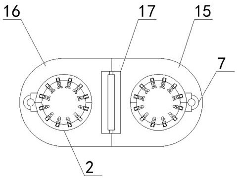
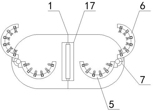
[0045] Such as Figure 1-7 As shown, this embodiment provides a massage device for leg health treatment, including a bracket 1, a cylinder body 2, a massage mechanism and a control mechanism, the control mechanism includes a processing unit 3 and a drive unit 4, and the processing unit 3 is connected with the drive unit 4, the bracket 1 includes two symmetrically designed frame grooves, the cylinder body 2 is arranged in the frame grooves, the bracket 1 is used to fix the cylinder body 2, the Both the top and the bottom of the cylinder 2 are provided with openings, the cylinder 2 includes a lower cylinder 5, an upper cylinder 6 and a first screwing device 7, the lower cylinder 5 and the upper cylinder 6 pass through The first screwing device 7 is connected, the first screwing device 7 is connected with the drive unit 4, and is used to control the opening and closing of the cylinder body 2, and the connection between the lower cylinder part 5 and the upper cylinder part 6 The ...
Embodiment 2
[0057] Such as Figure 8 As shown, the present embodiment provides a working method for a massage device for leg health treatment, including the following working steps:
[0058] S101: The processing unit 3 outputs a first opening signal to the driving unit 4, and the driving unit 4 drives the first screwing device 7 to rotate upward by 90 degrees;
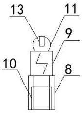
[0059] S102: The pressure sensor 13 detects a first force value of the bead-shaped massage body 11 and sends the first force value to the processing unit 3;
[0060] S103: The processing unit 3 extracts a first force value smaller than a first preset force value, and the telescopic device 10 corresponding to the first force value;
[0061] S104: The processing unit 3 outputs a first extension signal to the drive unit 4, and the drive unit 4 drives the telescopic device 10 to extend until the first force value corresponding to the telescopic device 10 is greater than or equal to the first preset force value;
[0062] S105: The p...
Embodiment 3
[0082] Such as Figure 5 , 7 As shown, when the user uses the pedal 14, the pressure sensor 13 on the pedal 14 simultaneously detects the third force value of the bead-shaped massage body 11 and sends the third force value to the processing unit 3;
[0083] The processing unit 3 extracts a third force value smaller than the first preset force value, and the telescopic device 10 corresponding to the third force value;
[0084] The processing unit 3 outputs a third extension signal to the driving unit 4, and the driving unit 4 drives the telescopic device 10 to extend until the third force value corresponding to the telescopic device 10 is greater than or equal to the first a preset force value;
[0085] The processing unit 3 outputs a massage signal to the driving unit 4, and the driving unit 4 drives the massage cylinder 9 to start.
[0086] Specifically, the pedal 14 is arranged on the bottom of the bracket 1, and the pedal 14 is movably connected with the bracket 1. When ...
PUM
 Abstract
Description
Claims
Application Information
 - R&D
- Intellectual Property
- Life Sciences
- Materials
- Tech Scout
- Unparalleled Data Quality
- Higher Quality Content
- 60% Fewer Hallucinations
Browse by: Latest US Patents, China's latest patents, Technical Efficacy Thesaurus, Application Domain, Technology Topic, Popular Technical Reports.
© 2025 PatSnap. All rights reserved.Legal|Privacy policy|Modern Slavery Act Transparency Statement|Sitemap|About US| Contact US: help@patsnap.com