Cardiovascular anti-blocking hydrops drainage device

A cardiovascular and scientific prevention technology, applied in the field of anti-blockage effusion drainage device in the cardiovascular department, can solve the problems of inability to effectively control the patient's effusion flow and flow rate, and the inability to ensure that the drainage tube will not be blocked.

Active Publication Date: 2021-01-01
HENAN MEDICAL COLLEGE
View PDF12 Cites 3 Cited by
  • Summary
  • Abstract
  • Description
  • Claims
  • Application Information

AI Technical Summary

Problems solved by technology

[0008] In view of the above situation, in order to overcome the defects of the prior art, the present invention provides an anti-clogging effusion drainage device for cardiovascular department, which effectively solves the problem that the existing drainage tube cannot effectively control the patient's effusion flow and flow rate, and at the same time cannot To ensure that the drainage tube will not be blocked

Method used


Image

  • Cardiovascular anti-blocking hydrops drainage device
  • Cardiovascular anti-blocking hydrops drainage device
  • Cardiovascular anti-blocking hydrops drainage device

Examples


Embodiment 1

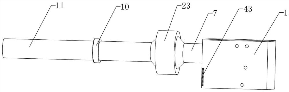
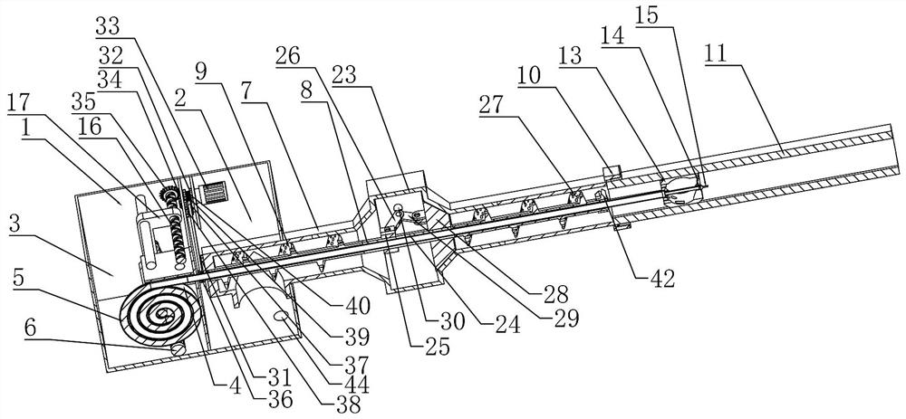
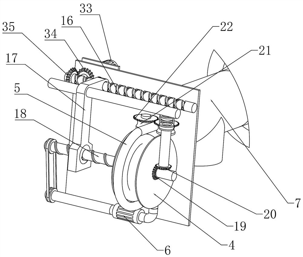
[0036] Embodiment 1, the present invention is an anti-blockage fluid drainage device in the Department of Cardiology, which includes a housing 1, and the housing 1 is used to provide fixed support for the subsequent structure. It is characterized in that the housing 1 There are negative pressure chamber 2 and water supply chamber 3 on the left and right sides respectively. The negative pressure chamber 2 is used to collect the effusion. At the same time, the negative pressure chamber 2 is fixedly connected with a negative pressure device to ensure the negative pressure. The chamber 2 is always in a low-pressure state, and the water supply chamber 3 is rotatably connected with a pipe collection disk 4, and the telescopic water pipe 5 is wound around the pipe collection disk 4, and the lower end of the telescopic water pipe 5 is fixedly connected to the The water supply pump 6 at the bottom of the water supply bin 3 is connected, the water supply bin 3 is filled with water, and t...

Embodiment 2

[0041] Embodiment 2, on the basis of Embodiment 1, when the telescopic water pipe 5 is retracted and retracted through the hydraulic pressure and the rotation of the pipe collection disc 4, there will be a problem of insufficient power, so this embodiment provides A telescopic water pipe 5 conveying and retracting driving device, specifically, the rear end of the pipe collection tray 4 is coaxially fixedly connected with a telescopic driving bevel gear 19, and a telescopic driven bevel gear is meshed beside the telescopic driving bevel gear 19 20. Drive the telescoping drive bevel gear 19 to rotate synchronously while the tube collection tray 4 is reversing forward and reverse, and then drive the telescopic driven gear to rotate synchronously;

[0042] The front and rear sides of the telescopic water pipe 5 are connected with driving friction wheels 21, and the upper ends of the two driving friction wheels 21 are fixedly connected with driving friction gears 22, and the two dri...

Embodiment 3

[0043] Embodiment 3, on the basis of Embodiment 2, for patients with different degrees, it is necessary to control the drainage speed of the effusion in the patient, so as to facilitate the control of the flow rate of the effusion, so this embodiment provides a flow rate control device, specifically Yes, there is a middle connecting pipe 23 fixedly connected between the connecting pipe 7 and the threaded joint 10, and the middle connecting pipe 23 is built with a fixed sleeve coaxially fixedly connected to the left end of the screw conveying paddle 9 shaft 24, so that the rotation of the screw conveying paddle 9 drives the said fixed sleeve shaft 24 to rotate synchronously, the described fixed sleeve shaft 24 is connected with the described connecting sleeve 8 in rotation, and the right end of the described fixed sleeve shaft 24 is fixed A fixed sleeve 25 is connected to drive the fixed sleeve 25 to rotate synchronously while the fixed sleeve shaft 24 rotates, and several first...


PUM


Abstract

The invention relates to a cardiovascular anti-blocking hydrops drainage device, and effectively solves the problems that an existing drainage tube cannot effectively control hydrops flow and flow velocity of a patient, and meanwhile, the drainage tube cannot be guaranteed not to be blocked. The technical scheme of the invention for solving the problems is that the cardiovascularanti-blocking hydrops drainage device comprises a shell; a negative pressure bin and a water supply bin are respectively formed on the left side and the right side inside the shell; the inside of the water supply bin is rotationally connected with a pipe collecting disc; the pipe collecting disc is wound with a telescopic water pipe; the lower end of the telescopic water pipe is connected with a water supply pump fixedly connected to the bottom of the water supply bin; the left side of the shell is fixedly connected with a communicating connecting pipe; the inside of the communicating connecting pipe is coaxially and fixedly connected with a connecting sleeve; the outer wall of the connecting sleeve is coaxially and rotationally connected with a spiral conveying paddle; the left end of the communicating connecting pipe is fixedly communicated with a threaded connector; the left end of the threaded connector is connected in a detachable mode with a flow guide pipe; the inside of the flow guide pipe is fixedly connected with a sliding rail; a sliding ball matched with the sliding rail is connected in a left-and-right sliding mode inside the flow guide pipe; and the telescopic water pipe at the left end is arranged in the connecting sleeve. The cardiovascular anti-blocking hydrops drainage device is concise in structure and high practicality.

Description

technical field [0001] The invention relates to the technical field of medical devices, in particular to an anti-blockage fluid drainage device for cardiovascular departments. Background technique [0002] Patients with cardiovascular diseases are prone to complications such as effusion in the affected area. During treatment, proper drainage of the effusion and blood in the affected area is a necessary prerequisite to ensure the smooth progress of the treatment. Drainage surgery is commonly used in cardiovascular medicine. One of the operations is to drain the fluid and blood in the affected area. [0003] At present, there are many problems in the process of drainage of effusion in patients: [0004] 1. Most of the existing effusion drainage equipment adopts the original intubation gravity drainage, which cannot effectively control the flow rate and flow rate of effusion drainage; [0005] 2. Viscous effusion will cause blockage of the drainage tube. It is necessary to re...

Claims


Application Information

Patent Timeline
Patent Type & Authority Applications(China)
IPC IPC(8): A61M1/00
CPCA61M1/0023A61M2205/3334A61M1/83A61M1/74A61M1/84
Inventor 薛红莉赵鹏张珊珊白辉辉雷延飞
Owner HENAN MEDICAL COLLEGE
Why Eureka
Try Eureka