Tracheal intubation method for mouse

A technique for endotracheal intubation and mice, which is applied in the fields of endotracheal intubation, medical science, and other medical devices. The effect of promotion

Pending Publication Date: 2021-01-01
AIR FORCE MEDICAL UNIV
View PDF0 Cites 1 Cited by
  • Summary
  • Abstract
  • Description
  • Claims
  • Application Information

AI Technical Summary

Problems solved by technology

[0004] 1) Unable to provide a continuous, sufficient and large operating space for glottic exposure, and for checking whether the endotracheal tube is in the trachea after endotracheal intubation
[0005] 2) Special epiglottis baffles, laryngoscopes and tracheal tubes are required, which is not c

Method used


Image

  • Tracheal intubation method for mouse
  • Tracheal intubation method for mouse
  • Tracheal intubation method for mouse

Examples


Embodiment 1

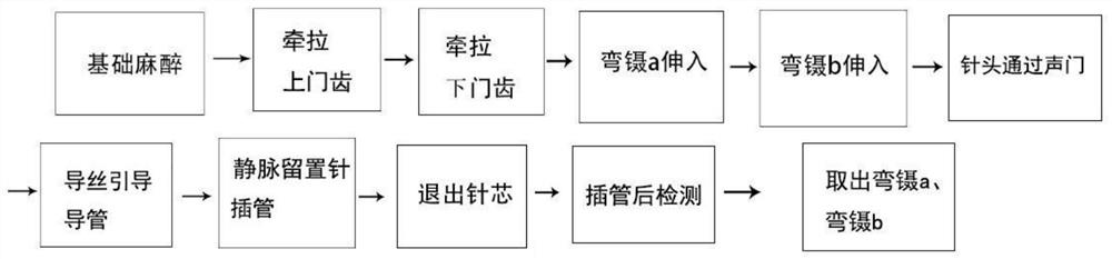
[0029] A kind of mouse tracheal intubation method of the present invention comprises the following steps:

[0030] Step 1, prepare a special experimental table, intravenous indwelling needle, curved forceps a, curved forceps b, cold light source, and mice;

[0031] Step 2, such as figure 1 As shown, the mice were intraperitoneally injected with sodium pentobarbital, the dose was 45 mg / kg, the concentration was 2%, and the dosage was 2.3 ml / kg. After basic anesthesia, the mice were fixed on a special experimental table, and the mouse's neck was tilted back 45° and the head was placed on the operating table 1 of the special experimental table;

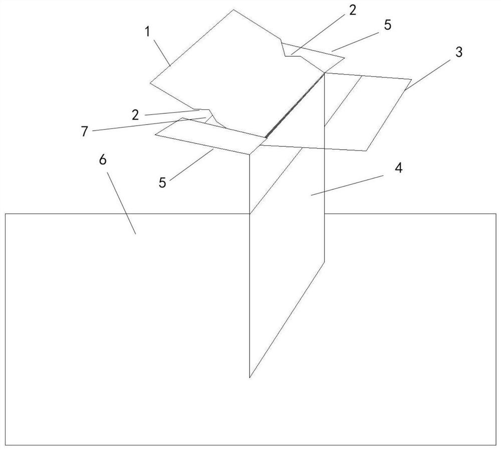
[0032] Step 3, such as figure 2 As shown, the two sides of the console 1 are provided with grooves 2 for winding rubber bands, and the rubber bands are used to pull the upper incisors of mice;

[0033] Step 4, such as figure 2 As shown, the console 1 is connected to the neutral plate 4 through hinges, and the two ends above the neu...

Embodiment 2

[0038] The present invention is a specially made test bench for mouse tracheal intubation method. The head end of the mouse is placed on the console 1 by tilting the neck of the mouse back by 45°. The two sides of the console 1 are provided with grooves for winding rubber bands, and the rubber bands pull the mice. The upper incisors of the console 1 are connected to the neutral board 4 through hinges, and the angle between the console 1 and the neutral board 4 is 45°; grooves 2 are arranged on both sides of the console 1 to wrap rubber bands, and the back of the console 1 is fixed by screws A finger joint plate, the length of the finger joint plate is greater than the length of the console 1; the horizontal plate 5 is fixed on both ends of the finger joint plate by bolts or glue, and the distance between the horizontal plate 5 at the two ends of the finger joint plate and the two sides of the console 1 is 1- 3cm; the neutral plate 4 is connected to the bottom plate 6 by welding...


PUM


Abstract

The invention discloses a tracheal intubation method for a mouse, and belongs to the field of tracheal intubation. The method comprises the steps: the neck of the mouse leans backwards for 45 degreeswith the head end located on an operation table; two sides of the operation table are each provided with a groove wound with a rubber band; the rubber bands are used for pulling upper incisors of themouse; the operation table is connected with a middle vertical plate; supporting frames are installed at two ends of the upper portion of the middle vertical plate; rubber ropes are wound around two sides of each supporting frame; the rubber ropes pull lower incisors of the mouse to open upper and lower jaw joints of the mouse; and cold light source is used for irradiating a position 0.5-1cm awayfrom the neck of the mouse; the tongue of the mouse is pulled out towards the left side; and bent tweezers a and bent tweezers b prop up the pharyngeal wall of the mouse to complete exposure of the glottis of the mouse. The invention provides the trachea intubation method that a special laryngoscope for rodents including mice and the like is not needed, the glottis is exposed more sufficiently, the intubation operation space is larger, and the success rate is higher.

Description

technical field [0001] The invention relates to the field of tracheal intubation, in particular to a mouse tracheal intubation method. Background technique [0002] Rodents such as mice and rats, especially mice, can be divided into three types of tracheal intubation methods: invasive, minimally invasive and noninvasive. The invasive tracheal intubation method mainly adopts tracheotomy, in which a tracheal tube is inserted, and a ventilator is connected externally, which is mainly suitable for acute animal experiments. Minimally invasive tracheal intubation mainly uses neck skin incision to expose the trachea, and intubation is carried out through the mouth under the condition of looking directly at the trachea. This method can be used for chronic animal experiments, such as the preparation of a mouse model of myocardial infarction. The non-invasive tracheal intubation method requires the use of a special laryngoscope. The endotracheal tube is sent into the mouse trachea un...

Claims


Application Information

Patent Timeline
IPC IPC(8): A61M16/04A61D3/00
CPCA61M16/04A61D3/00A61M2250/00
Inventor 韩勇周永生宋海龙熊延路乔天运冯杨波卢昌波孟凡成徐晖
Owner AIR FORCE MEDICAL UNIV
Why Eureka
Try Eureka