
Tailstock type vertical take-off and landing unmanned aerial vehicle and control method thereof

A technology for vertical take-off and landing and unmanned aerial vehicles, which is applied in the field of aviation aircraft and unmanned aerial vehicles, and can solve the problems of increasing the resistance of unmanned aerial vehicles, radar reflection cross section, large space and specific gravity, and complexity.

Active Publication Date: 2021-01-01
ZHEJIANG UNIV
View PDF13 Cites 9 Cited by
  • Summary
  • Abstract
  • Description
  • Claims
  • Application Information

AI Technical Summary

Problems solved by technology

[0003] Tilting rotor is currently the most widely studied vertical take-off and landing-high-speed cruise technology. The conversion of vertical take-off and landing and cruise modes is realized through the tilting mechanism of the engine or rotor, although this method can realize the control of helicopters and fixed-wing UAVs. Complementary advantages, but due to the complex wing surface and tilting mechanism, the drag and radar reflection cross section (RCS) of the UAV are greatly increased, which reduces its cruise capability and stealth performance
The U.S. Navy’s F35C carrier-based fighter jet achieves vertical take-off and landing through engine vector nozzles, lift fans and nozzles placed on the wing surface, but its control system is complex, and the special lift fans occupy a large space and proportion during the take-off and landing phase. , and the control difficulty is high, which makes it difficult to popularize and use this scheme on other models

Method used


Image

  • Tailstock type vertical take-off and landing unmanned aerial vehicle and control method thereof
  • Tailstock type vertical take-off and landing unmanned aerial vehicle and control method thereof
  • Tailstock type vertical take-off and landing unmanned aerial vehicle and control method thereof

Examples


Embodiment Construction

[0032] The present invention will be further elaborated and illustrated below in conjunction with the accompanying drawings and specific embodiments. The technical features of the various implementations in the present invention can be combined accordingly on the premise that there is no conflict with each other.

[0033] The invention proposes a tailseat type vertical take-off and landing unmanned aerial vehicle and its control method. The unmanned aerial vehicle can give full play to the vertical The take-off and landing function and the high-speed cruise function of the fixed wing provide technical support for safe take-off and landing in complex environments such as seas and mountains. The specific implementation method is as follows:

[0034] The specific implementation is as follows:

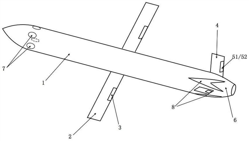
[0035] The structural principle of a tail seat type vertical take-off and landing UAV is as attached figure 1 As shown, it is mainly composed of the following main parts: fuselage 1, wi...


PUM


Abstract

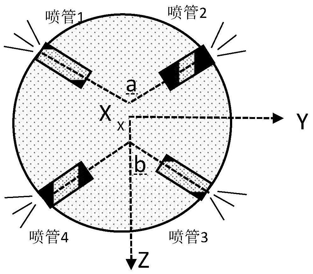
The invention relates to a tailstock type vertical take-off and landing unmanned aerial vehicle and a control method thereof. The unmanned aerial vehicle is mainly composed of a fuselage, wings, ailerons, an empennage, an elevator, a rudder, an engine, posture adjusting spray pipes, an undercarriage and the like. The wings are symmetrically arranged on the two sides of the middle of the fuselage.The ailerons are hinged to the rear edges of the wings on two sides; the empennage is positioned at the tail part of the fuselage and can adopt a form of a vertical fin and a horizontal fin or a V-shaped empennage; the elevator and the rudder are hinged to the rear edge of the empennage; the engine is arranged at the tail of the fuselage and generates main thrust. The posture adjusting spray pipesare distributed on the outer surface of the front portion of the fuselage and can spray air outwards to generate rotating torque to assist in adjusting the posture of the unmanned aerial vehicle. Theundercarriage is arranged at the tail of the fuselage, can be automatically folded and unfolded and is used for supporting the unmanned aerial vehicle to achieve vertical take-off and landing of theunmanned aerial vehicle. The tailstock type vertical take-off and landing unmanned aerial vehicle designed by the invention can realize tailstock type vertical take-off and landing and high-speed cruise through coordination control among the posture adjusting spray pipes, the engine, the pneumatic control surface and the undercarriage.

Description

technical field [0001] The invention relates to the fields of unmanned aerial vehicles and aviation aircraft, in particular to a vertical take-off and landing unmanned aerial vehicle and a control method thereof. Background technique [0002] In recent years, with the widespread application of UAVs in various fields of military and civilian use, its use environment and operational tasks have become increasingly complex. The convenience and safety of the take-off and landing scheme are important factors that determine the continuous operation capability of UAVs in harsh environments such as seas and mountains. Therefore, the functional characteristics of vertical take-off and landing are of great significance to the application expansion of UAVs. Helicopters and fixed-wing UAVs have their own advantages in vertical take-off and landing and high-speed cruise respectively, and how to fully combine these two advantages will be the core issue that determines the initiative of fut...

Claims


Application Information

Patent Timeline
Patent Type & Authority Applications(China)
IPC IPC(8): B64C3/40B64C3/56B64C5/00B64C25/10B64C29/00B64C1/06B64C15/00
CPCB64C3/40B64C3/56B64C5/00B64C25/10B64C29/00B64C1/068B64C15/00
Inventor 赵文杰陈征邵雪明黎军
Owner ZHEJIANG UNIV
Learn More