Cargo loading and unloading equipment for road transportation

A cargo loading and unloading and road technology, which is applied in the field of cargo loading and unloading, can solve the problems of easy falling of cargo, low work efficiency, high cost, etc., and achieve the effect of increasing the contact area, saving manpower, and avoiding damage

Inactive Publication Date: 2021-01-01
湖南新正渣土有限公司
View PDF0 Cites 0 Cited by
  • Summary
  • Abstract
  • Description
  • Claims
  • Application Information

AI Technical Summary

Problems solved by technology

[0002] Road transport refers to the general term for the use of cars or other means of transport on public roads to engage in passenger or cargo transport and related business activities. Since road transport is less affected by climate and natural conditions, and the transport capacity and single-vehicle load are large, in The regularity and low cost of transportation have taken advantage, coupled with various types of vehicles, it can carry almost any commodity, and it is almost not limited by weight and volume. During the transportation of goods, it is usually necessary to check the goods For loading and unloading operations, traditional manual handling is used, but the work efficiency is low and the cost is high. The existing road transport loading and unloading equipment cannot clamp the goods when disassembling and assembling, which makes it easy to lift and lower the goods. drop, use poorly

Method used


Image

  • Cargo loading and unloading equipment for road transportation
  • Cargo loading and unloading equipment for road transportation
  • Cargo loading and unloading equipment for road transportation

Examples


Embodiment Construction

[0019] The following will clearly and completely describe the technical solutions in the embodiments of the present invention with reference to the accompanying drawings in the embodiments of the present invention. Obviously, the described embodiments are only some, not all, embodiments of the present invention.

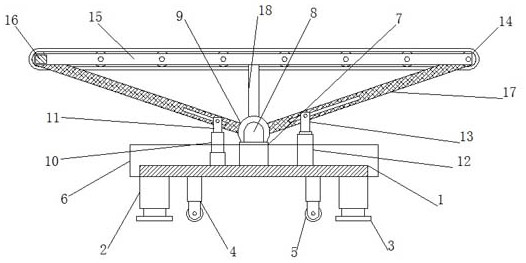
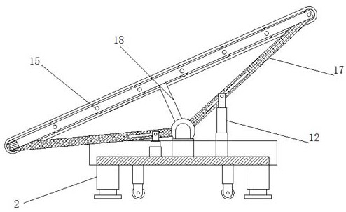
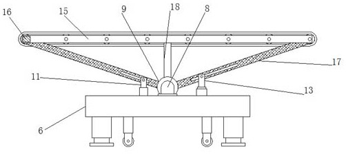
[0020] refer to Figure 1-3 , a kind of cargo handling equipment for road transportation, comprising a bottom plate 1, hydraulic cylinders 2 are fixedly connected to the four corners of the bottom of the bottom plate 1, and a support piece 3 is fixedly connected to the bottom of the hydraulic cylinder 2, and the bottom of the bottom plate 1 is close to the hydraulic cylinder The four corners of 2 are fixedly connected with supporting columns 4, and the bottom of supporting columns 4 is fixedly connected with universal wheels 5, and the outer walls of both sides of the bottom plate 1 are fixedly connected with supporting plates 6, and the top middle position of the bot...


PUM


Abstract

The invention discloses cargo loading and unloading equipment for road transportation. The cargo loading and unloading equipment comprises a bottom plate, wherein hydraulic oil cylinders are fixedly connected to four corners of the bottom of the bottom plate, and supporting sheets are fixedly connected to the bottoms of the hydraulic oil cylinders; supporting plates are fixedly connected to the outer walls of two sides of the bottom plate, and a supporting block is fixedly connected to the middle position of the top of the bottom plate; a U-shaped rod is fixedly connected to the top of the supporting block, and a bearing is connected to the top of the U-shaped rod in a sleeving manner; a first push rod motor is arranged on one side of the supporting block, and a first U-shaped plate is fixedly connected to the top of the first push rod motor; and a second push rod motor is arranged on the other side of the supporting block. According to the cargo loading and unloading equipment disclosed by the invention, the height of the loading and unloading equipment can be adjusted through the hydraulic oil cylinders, and the contact area of the loading and unloading equipment and the ground can be increased through the supporting sheets at the bottoms of the hydraulic oil cylinders, so that the stability of fixing the loading and unloading equipment is facilitated, and the circumstance that the ground is damaged during loading and unloading of cargoes is avoided; and universal wheels at the bottom of the loading and unloading equipment are favorable for operators to move the loading and unloading equipment.

Description

technical field [0001] The invention relates to the technical field of cargo handling, in particular to a cargo handling equipment for road transport. Background technique [0002] Road transport refers to the general term for the use of cars or other means of transport on public roads to engage in passenger or cargo transport and related business activities. Since road transport is less affected by climate and natural conditions, and the transport capacity and single-vehicle load are large, in The regularity and low cost of transportation have taken advantage, coupled with various types of vehicles, it can carry almost any commodity, and it is almost not limited by weight and volume. During the transportation of goods, it is usually necessary to check the goods For loading and unloading operations, traditional manual handling is used, but the work efficiency is low and the cost is high. The existing road transport loading and unloading equipment cannot clamp the goods when ...

Claims


Application Information

Patent Timeline
Patent Type & Authority Applications(China)
IPC IPC(8): B65G65/06B65G41/00
CPCB65G41/00B65G65/06
Inventor 王义
Owner 湖南新正渣土有限公司
Why Eureka
Try Eureka