
Mounting device for prefabricated building prefabricated component

A technology of prefabricated components and installation equipment, which is applied in the direction of building construction, construction, and building materials processing, etc. It can solve problems such as low efficiency, time-consuming and labor-consuming efficiency, and falling of prefabricated components in prefabricated buildings, so as to prevent shaking and ensure The effect of efficient installation

Active Publication Date: 2021-01-01
湖南铂尚建设工程有限公司
View PDF9 Cites 3 Cited by
  • Summary
  • Abstract
  • Description
  • Claims
  • Application Information

AI Technical Summary

Problems solved by technology

[0003] During the assembly process of the existing prefabricated building components, cranes are used to lift the prefabricated building components, and then manual erection and installation are carried out. In the process, there will be the following problems: (1) During the process of hoisting the prefabricated building components by the crane (long-distance lifting), it is easy to cause the prefabricated building components to shake. The prefabricated components of the building fall, which brings certain safety hazards; (2) when the crane lifts the prefabricated building components to the corresponding installation position, manual positioning is required. During the positioning process, operators and The crane operator must communicate continuously to complete the positioning and installation. In this process, there are problems of time-consuming, labor-intensive and low efficiency

Method used


Image

  • Mounting device for prefabricated building prefabricated component
  • Mounting device for prefabricated building prefabricated component
  • Mounting device for prefabricated building prefabricated component

Examples


Embodiment Construction

[0036] Attached below Figure 1-6 The present invention is further described with embodiment:

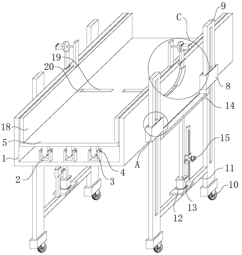
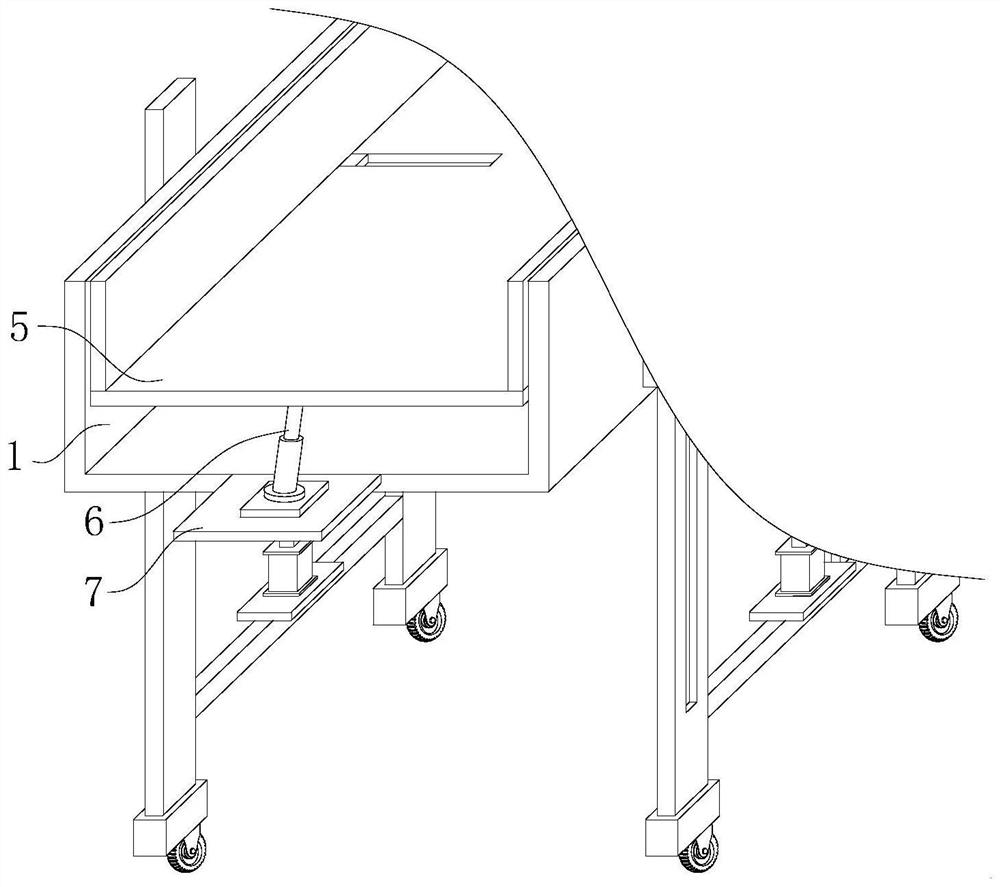
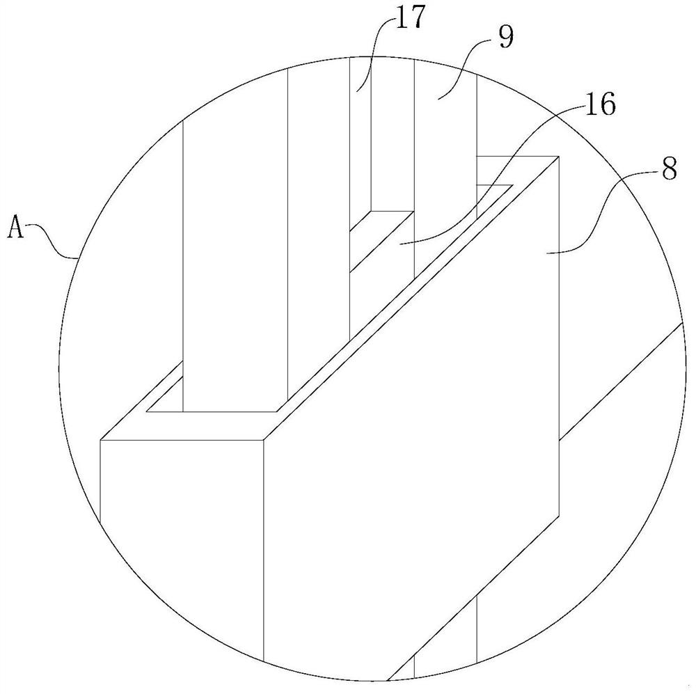
[0037] An installation device for prefabricated building components, comprising an assembly installation groove 1 and a support support plate 5, the support support plate 5 is movably arranged in the assembly installation groove 1, and one end of the support support plate 5 is connected with several The rotating support column 3 is fixedly inserted with the rotating rod 4, and the rotating rod 4 is rotated and arranged in the fixed supporting groove 2, and the fixed supporting groove 2 is fixedly arranged on the inner bottom wall of the assembly installation groove 1, and the supporting bearing The other end of the supporting plate 5 is hinged with one end of the hydraulic cylinder 6, and the other end of the hydraulic cylinder 6 is rotatably arranged on the upper end surface of the fixed plate 7, and the fixed plate 7 is fixedly arranged on the side wall of the assembly groove 1. ...


PUM


Abstract

The invention relates to a mounting device for a prefabricated building prefabricated component. The mounting device comprises an assembly mounting groove and a supporting bearing plate, wherein the supporting bearing plate is movably arranged in the assembly mounting groove, a plurality of rotary supporting columns are connected to one end of the supporting bearing plate, and rotating rods are fixedly inserted into the rotary supporting columns. The mounting device is used for clamping, fixing and lifting the prefabricated building prefabricated component in the mounting process, specifically, in the mounting process of the prefabricated building prefabricated component, the prefabricated building prefabricated component is clamped and fixed from the bottom through the device, then the prefabricated building prefabricated component is lifted to the corresponding mounting position through the equipment, and finally the device can drive the prefabricated building prefabricated componentto rotate, so that the prefabricated building component is in a vertical state; and meanwhile, the device can also achieve a rapid positioning effect, so that the working efficiency can be effectively improved.

Description

technical field [0001] The invention relates to the technical field of prefabricated buildings, in particular to an installation device for prefabricated components of a prefabricated building. Background technique [0002] A building assembled on site by prefabricated components is called a prefabricated building. According to the form and construction method of prefabricated components, it is divided into five types: block building, plate building, box building, skeleton plate building and rising plate building. With the development of modern industrial technology, building houses can be manufactured in batches and in sets like machine production. As long as the prefabricated building components are transported to the construction site and assembled, the prefabricated building began to arouse people's interest in the early 20th century, and finally realized it in the sixties. Britain, France, the Soviet Union and other countries first made attempts. Due to the fast cons...

Claims


Application Information

Patent Timeline
IPC IPC(8): B66F7/20B66F7/22B66F7/28E04G21/16
CPCB66F7/20B66F7/22B66F7/28E04G21/162
Inventor 陈志兴
Owner 湖南铂尚建设工程有限公司
Learn More