Concrete vibrating rod inserting and pulling speed regulating device for building construction

A technology of building construction and speed control device, applied in construction, building structure, processing of building materials, etc., can solve problems such as operation errors, concrete holes, and high requirements for workers' operating experience, so as to reduce the difficulty of operation, avoid skew, Guaranteed effect of vibrating effect

Inactive Publication Date: 2021-01-01
徐州易尚饰家装饰工程有限责任公司
View PDF1 Cites 3 Cited by
  • Summary
  • Abstract
  • Description
  • Claims
  • Application Information

AI Technical Summary

Problems solved by technology

[0002] At present, in the process of cable layout, some cables need to be suspended and fixed from a high place. The existing suspension is currently in the process of building construction. Generally, during pouring, manual hand-held vibrating rods are used to insert them into the concrete for vibrating work. When using the vibrating rods, it is necessary to follow the operation method of quick insertion and slow removal. The quick insertion is to prevent the surface layer from being vibrated. The concrete is vibrated first, and delamination and segregation occur with the lower concrete, and the slow pulling is to make the concrete have time to fill the cavity formed when the vibrator is pulled out, and because the quick insertion and slow removal are all done manually, the Workers have high requirements for operating experience, and it is difficult to accurately control the speed of slow pulling when manual slow pulling is performed, resulting in operational errors and resulting in holes in the concrete

Method used


Image

  • Concrete vibrating rod inserting and pulling speed regulating device for building construction
  • Concrete vibrating rod inserting and pulling speed regulating device for building construction
  • Concrete vibrating rod inserting and pulling speed regulating device for building construction

Examples


Embodiment Construction

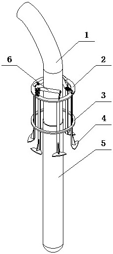
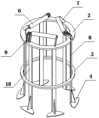
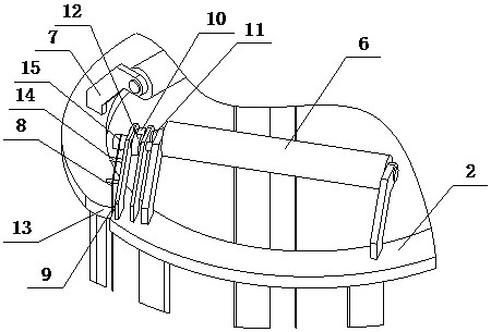
[0016] A kind of concrete vibrating rod plug-in speed regulating device for building construction of the present invention is realized in this way: a kind of concrete vibrating rod plug-in speed regulating device for building construction of the present invention is made up of main body device and speed regulating device, and main body device is supported by Plate (2), counterweight ring (3), bottom support (4) and connection plate (18), the support plate (2) is an annular plate structure, one end of a plurality of connection plates (18) and the support The bottoms of the boards (2) are equiangularly connected, the other end of the connecting board (18) extends downwards, and the bottom brace (4) is placed on the other end of the connecting board (18), the bottom brace (4) and There are reinforcing ribs between the connecting plates (18), the counterweight ring (3) is located under the support plate (2), and is close to the other end of the connecting plate (18), and the guide ...


PUM


Abstract

The invention relates to a concrete vibrating rod inserting and pulling speed regulating device for building construction, and discloses a speed regulating device. The speed regulating device regulates the inserting and pulling speed of a vibrating rod through a ratchet wheel and pawl structure, can form angle guide when the vibrating rod is inserted, and is characterized in that a supporting plate is of an annular plate-shaped structure, one ends of multiple connecting plates are connected with the bottom of the supporting plate at equal angles, the other ends of the connecting plates extenddownwards, bottom supporting feet are arranged at the other ends of the connecting plates, reinforcing ribs are arranged between the bottom supporting feet and the connecting plates, a balance weightring is located below the supporting plate and close to the other ends of the connecting plates, and at least three fixing frames are arranged on the supporting plate at equal angles; and the fixing frames are composed of two fixing plates, one ends of the fixing plates are fixedly connected with the top of the supporting plate, the other ends of the fixing plates extend obliquely upwards close tothe center line of the supporting plate, guide rollers are arranged on the fixing frames through roller shafts, a plurality of anti-skid strips are arranged on the guide rollers, and ratchet wheels are arranged at the positions, close to a supporting frame, of the roller shafts.

Description

technical field [0001] The invention relates to a speed regulating device for inserting and pulling out concrete vibrating rods for building construction, which relates to a device for regulating speed when inserting and pulling out concrete vibrating rods in building construction, and belongs to the field of construction engineering equipment. In particular, it relates to a speed regulating device for adjusting the speed of the insertion and withdrawal of the vibrating rod through a ratchet and pawl structure, and capable of forming an angle guide when the vibrating rod is inserted. Background technique [0002] At present, in the process of cable layout, some cables need to be suspended and fixed from a high place. The existing suspension is currently in the process of building construction. Generally, during pouring, manual hand-held vibrating rods are used to insert them into the concrete for vibrating work. When using the vibrating rods, it is necessary to follow the op...

Claims


Application Information

Patent Timeline
Patent Type & Authority Applications(China)
IPC IPC(8): E04G21/08
CPCE04G21/08
Inventor 不公告发明人
Owner 徐州易尚饰家装饰工程有限责任公司
Why Eureka
Try Eureka