
Pressure-resistant double-layer conveying pipeline

A double-layer transportation and pipeline technology, which is applied in the field of deep water equipment and petrochemical transportation equipment, can solve the problems of large fluid consumption, pipeline buckling, pollution damage, etc., and achieve the effect of reducing production costs and enhancing adaptability

Active Publication Date: 2021-01-01
东营新达德安新材料科技有限责任公司
View PDF16 Cites 0 Cited by
  • Summary
  • Abstract
  • Description
  • Claims
  • Application Information

AI Technical Summary

Problems solved by technology

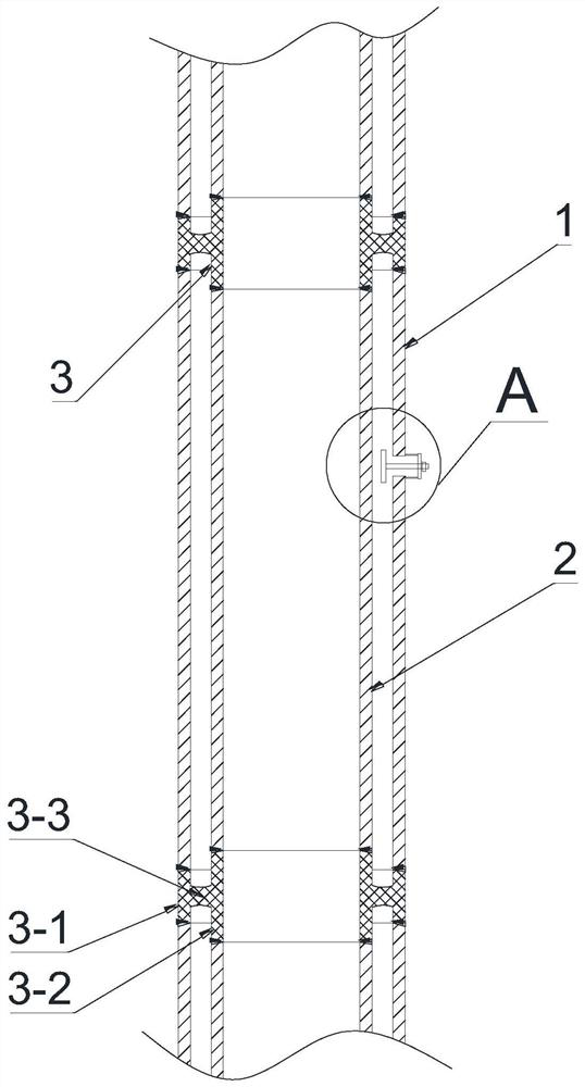
[0003] There are still many problems in the laying and operation of the current deep sea submarine oil pipeline. On the one hand, fluid is generally injected into the annular space between the inner pipe and the outer pipe to generate a certain static pressure, which consumes a large amount of fluid and makes the overall weight of the pipeline On the other hand, there is the problem of pipeline buckling. When the external water pressure of the pipeline is too large or when a collision occurs, the pipeline will sag and buckle, and the buckling propagation speed is very fast. When buckling occurs at a certain point of the pipeline, the buckling change will follow Its length direction propagates at a speed of hundreds of meters per second, causing the entire pipeline structure to fail and damage, causing huge economic losses, and the leakage of oil in the pipeline will also cause pollution and damage to the ecological environment

Method used


Image

  • Pressure-resistant double-layer conveying pipeline
  • Pressure-resistant double-layer conveying pipeline
  • Pressure-resistant double-layer conveying pipeline

Examples


Embodiment Construction

[0023] The present invention will be further described in detail below in conjunction with the accompanying drawings and embodiments.

[0024] The implementation method of the present invention is illustrated by specific specific examples below, and those skilled in the art can easily understand other advantages and effects of the present invention from the content disclosed in this specification.

[0025] Referring to the accompanying drawings, the structures, proportions, sizes, etc. shown in the accompanying drawings of this specification are only used to match the content disclosed in the specification, for those who are familiar with this technology to understand and read, and are not used to limit the scope of the present invention. Therefore, it has no technical substantive meaning, and any modification of structure, change of proportional relationship or adjustment of size shall still fall within the scope of The technical content disclosed in the present invention mus...


PUM


Abstract

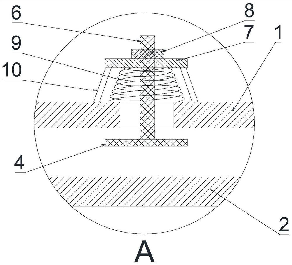
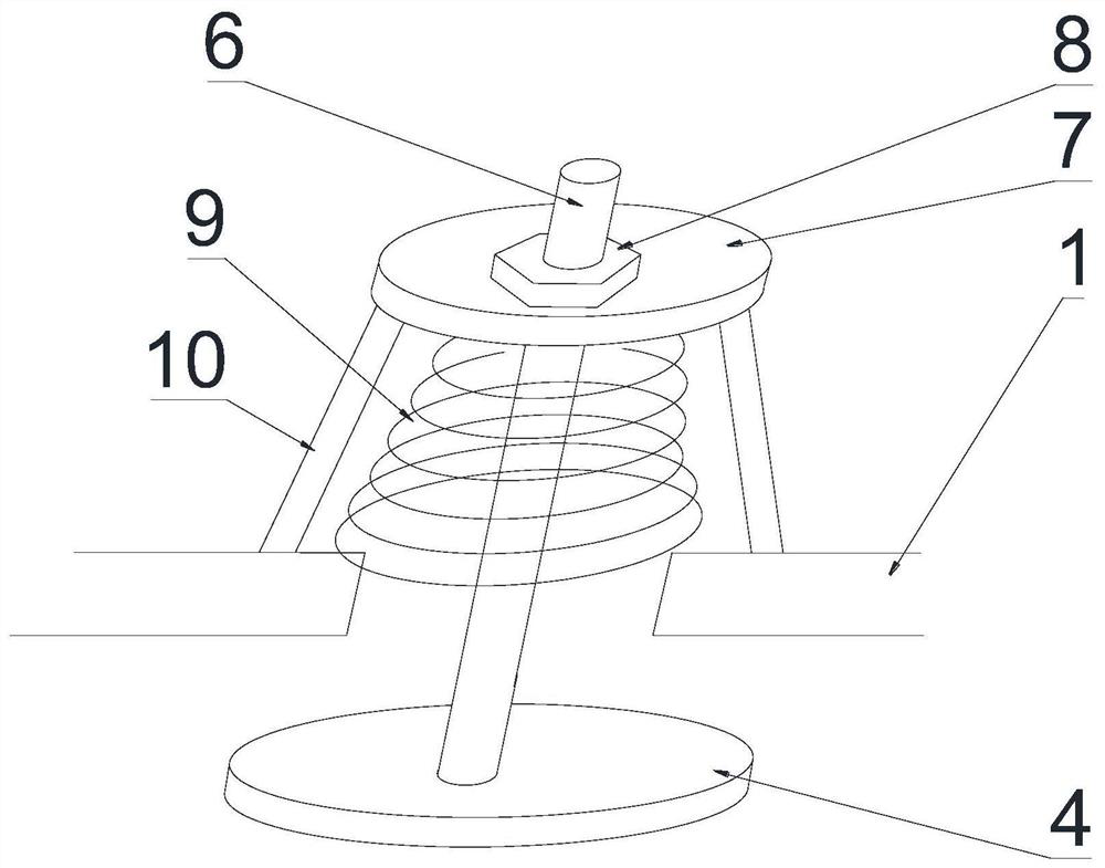
The invention aims to provide a pressure-resistant double-layer conveying pipeline. Seawater is directly adopted for filling in the process that the pipeline is installed and sinks into the seabed, the total weight in the transportation and hoisting process is reduced, and meanwhile the working procedure and cost increase caused by direct liquid filling in the production process is reduced. The pressure-resistant double-layer conveying pipeline comprises an inner pipe, an outer pipe and a bending stopping device, wherein the inner pipe is formed by splicing a plurality of inner pipe sections;the outer pipe is formed by splicing a plurality of outer pipe sections; the bending stopping device comprises an outer pipe connecting ring, an inner pipe connecting ring and a supporting body; the outer pipe is further provided with an automatic water filling valve; and the automatic water filling valve controls seawater to be automatically filled into an annular space between the inner pipe andthe outer pipe in the process that the pipeline sinks into the seabed, and therefore the pressure influence of seawater static pressure on the pipeline is relieved.

Description

technical field [0001] The invention belongs to the technical field of petrochemical transportation equipment and deep water equipment, and in particular relates to a pressure-resistant double-layer transportation pipeline. Background technique [0002] Pipeline and line transportation are the lifeblood of the energy industry. The initial infrastructure and later operation and maintenance processes require a lot of investment, and pipeline failures will also cause huge economic losses. With the development of offshore oil and gas, the demand for pipeline transportation between the sea and land is getting higher and higher, so the submarine oil pipeline was born. Deep sea oil pipelines are generally composed of inner pipes and outer pipes, and the inner pipes play the role of transporting oil and gas. , the outer tube is used to protect the inner tube to prevent the pipeline from being damaged under the action of internal oil pressure and external deep sea water pressure. ...

Claims


Application Information

Patent Timeline
Patent Type & Authority Applications(China)
IPC IPC(8): F16L9/18F16L55/07F16K17/04F16K1/00F16K1/32
CPCF16L9/18F16L55/07F16K17/0413F16K1/00F16K1/32
Inventor 杨新超
Owner 东营新达德安新材料科技有限责任公司
Learn More