Internet-Based Hidden Projector

A hidden projector technology, applied in instruments, projection devices, optics, etc., can solve the problems of shortened service life of equipment, affecting the appearance of the office, inconvenient disassembly and maintenance, etc., to prevent dust accumulation, improve automation control rate, Effects that are easy to manipulate

Active Publication Date: 2022-01-25
合肥华筑博展文化科技有限公司
View PDF18 Cites 0 Cited by
  • Summary
  • Abstract
  • Description
  • Claims
  • Application Information

AI Technical Summary

Problems solved by technology

Generally, the projector in the office is installed on the ceiling and connected by bolts. When the projector breaks down, it is inconvenient to disassemble and maintain, and the projector is exposed outside. When not in use, it will affect the overall appearance of the office, and it is easy to accumulate dust. Too much will easily lead to a shortened service life of the equipment, and the function is single, so a multi-functional hidden projector is proposed to solve the above-mentioned problems

Method used


Image

  • Internet-Based Hidden Projector
  • Internet-Based Hidden Projector
  • Internet-Based Hidden Projector

Examples


Embodiment 1

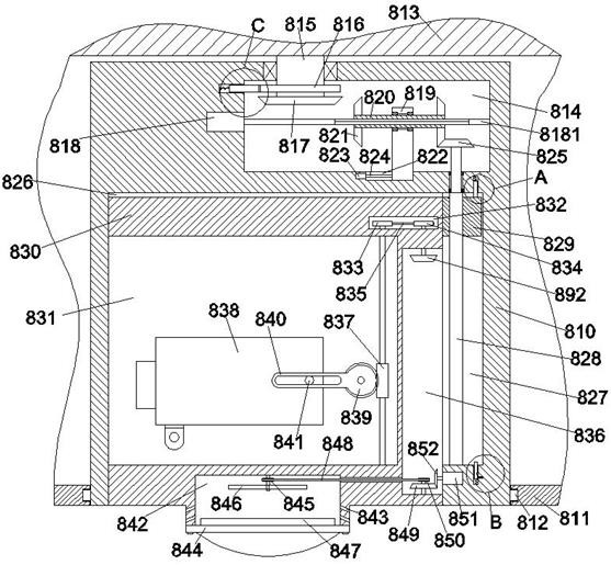
[0026] When lighting needs to be used, the indoor lighting work is realized through the ceiling lamp 844. When the ceiling lamp 844 works for a long time, the heat generated by the ceiling lamp 844 is absorbed by the heat sink 847, and then passed through the sixth bevel gear 852 on the joint control motor 851. Drive the fifth bevel gear 849 to rotate, and then the fourth pulley 850 on the fifth bevel gear 849 drives the first pulley 845 and the cooling blade 846 to rotate through the second belt 848, so that the heat on the cooling fin 847 passes through the cooling hole 843 Discharge, and then achieve rapid cooling work.

Embodiment 2

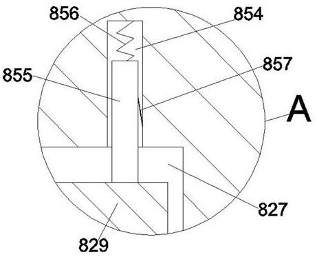
[0028] When projection work is required, the adjustment screw 824 is controlled by the adjustment motor 823 to rotate, so that the adjustment screw 824 drives the adjustment slider 819 to move to the rightmost position in the limit slip groove 822. At this time, the adjustment slider 819 drives the spline sleeve The second bevel gear 821 on the right side of the cylinder 820 is meshed with the third bevel gear 825. At the same time, the second bevel gear 821 on the left side of the spline sleeve 820 is kept away from the first bevel gear 817, and then the spline is driven by the driving motor 818. The rotating shaft 8181 rotates, and the splined sleeve 820 and the second bevel gear 821 are driven by the spline rotating shaft 8181 to rotate, and the second bevel gear 821 on the right side drives the third bevel gear 825 and the lifting screw 828 to rotate, so that the lifting screw 828 drives the guide The slide block 829 slides toward the bottom in the guide chute 827 until the...

Embodiment 3

[0030] When it needs to be packed up, the adjustment screw 824 is controlled by the adjustment motor 823 to rotate, so that the adjustment screw 824 drives the adjustment slider 819 to move to the rightmost position in the limit slip groove 822. At this time, the adjustment slider 819 drives the spline sleeve The second bevel gear 821 on the right side of the cylinder 820 is meshed with the third bevel gear 825. At the same time, the second bevel gear 821 on the left side of the spline sleeve 820 is kept away from the first bevel gear 817, and then the spline is driven by the driving motor 818. The rotating shaft 8181 rotates, the splined sleeve 820 and the second bevel gear 821 are driven by the spline rotating shaft 8181 to rotate, and the second bevel gear 821 on the right side drives the third bevel gear 825 and the lifting screw 828 to rotate in reverse, and then the lifting screw 828 drives the guide slider 829 to slide upwards, so that the top end of the guide slider 829...


PUM


Abstract

The invention discloses a hidden projector based on the Internet, which includes a housing housing, the housing housing is provided with a lifting chamber with an opening downward, and a lifting housing is slidably connected to the lifting chamber, and the lifting chamber is The right side wall is connected with a guide chute, the top of the lifting chamber is provided with a driving control room, and the driving control room is provided with a power drive mechanism, and the lifting housing is provided with a placement cavity with an opening to the left. The projection main body is hingedly connected to the placement cavity, and the slide guide block is fixedly connected to the right side end surface of the lifting housing by sliding fit in the slide guide groove. The bottom end surface of the placement cavity is provided with a heat dissipation chamber with an opening downward, the bottom of the heat dissipation chamber is fixed with a ceiling lamp, and the guide chute is also provided with a The transmission control mechanism, the device can automatically control the orientation and angle adjustment of the projector main body.

Description

technical field [0001] The invention relates to the technical field of projection equipment, in particular to an Internet-based hidden projector. Background technique [0002] A projector, also known as a projector, is a device that can project images or videos onto a screen. It can be connected to a computer, VCD, DVD, BD, game console and DV through different interfaces to play the corresponding video signal. Projectors are currently widely used in homes, offices, schools, and entertainment venues. According to different working methods, there are different types such as CRT, LCD, and DLP. Generally, the projector in the office is installed on the ceiling and connected by bolts. When the projector breaks down, it is inconvenient to disassemble and maintain, and the projector is exposed outside. When not in use, it will affect the overall appearance of the office, and it is easy to accumulate dust. Too much is likely to shorten the service life of the equipment, and the fu...

Claims


Application Information

Patent Timeline
Patent Type & Authority Patents(China)
IPC IPC(8): G03B21/14G03B21/16
CPCG03B21/145G03B21/16
Inventor 汪涛
Owner 合肥华筑博展文化科技有限公司
Why Eureka
Try Eureka