Eureka AIR delivers breakthrough ideas for toughest innovation challenges, trusted by R&D personnel around the world.

Fluid chemical raw material rapid cooling device

A chemical raw material, rapid cooling technology, applied in cooling fluid circulation devices, household refrigeration devices, coolers, etc., can solve the problem of slow cooling speed

Active Publication Date: 2021-05-11
淄博天丹化工有限公司
View PDF11 Cites 0 Cited by
  • Summary
  • Abstract
  • Description
  • Claims
  • Application Information

AI Technical Summary

Problems solved by technology

[0003] Some chemical raw materials are in a fluid state. When collecting and storing such chemical raw materials, the chemical raw materials need to be cooled first, and then the chemical raw materials after cooling are collected. Currently, when cooling fluid chemical raw materials, Usually, the chemical raw materials are directly contacted with the cold air to cool the chemical raw materials. Although the chemical raw materials can be cooled in this way, the cooling speed is relatively slow.

Method used


Image

  • Fluid chemical raw material rapid cooling device
  • Fluid chemical raw material rapid cooling device
  • Fluid chemical raw material rapid cooling device

Examples


Embodiment 1

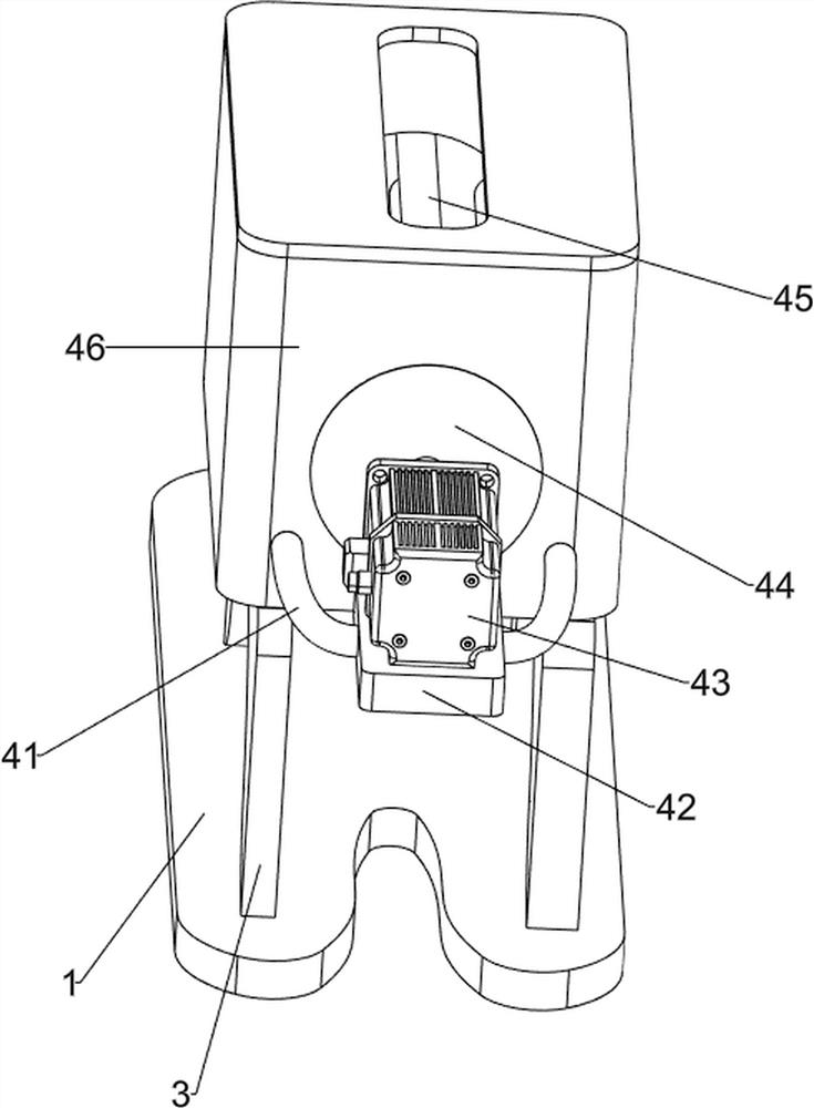
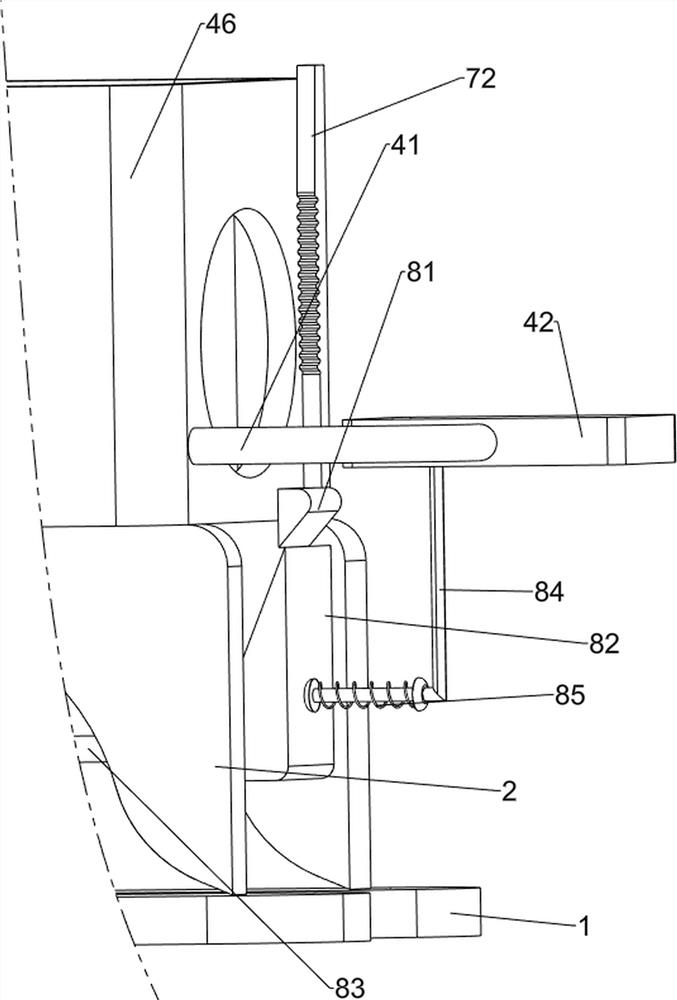
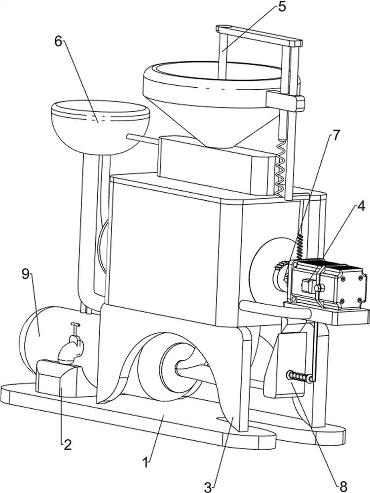
[0027] A rapid cooling device for fluid chemical raw materials, such as Figure 1 to Figure 3 As shown, it includes a base plate 1, a first support column 2, a second support column 3, a rolling mechanism 4 and a feeding mechanism 5. The left part of the base plate 1 is provided with the first support column 2, and the right part of the base plate 1 is provided with both front and rear sides. There is a second supporting column 3, a rolling mechanism 4 is arranged between the upper parts of the second supporting column 3, and a feeding mechanism 5 is arranged on the rolling mechanism 4.

[0028] When it is necessary to cool the fluid chemical raw materials, the fluid chemical raw materials are first poured into the feeding mechanism 5, and then the fluid chemical raw materials enter the rolling mechanism 4 through the feeding mechanism 5, and the fluid chemical raw materials are cooled by the rolling mechanism 4. The auxiliary cooling of the raw materials is carried out. After...

Embodiment 2

[0034] On the basis of Example 1, such as figure 1 , Figure 4 , Figure 5 , Image 6 and Figure 7 As shown, a refrigeration mechanism 6 is also included. The refrigeration mechanism 6 includes a condenser 61, a first condensation pipe 62, a second condensation pipe 63, a third condensation pipe 64, a second connecting rod 65 and a second condensation box 66. The left part of a condenser box 51 is connected with a first condenser pipe 62, the left part of the first condenser pipe 62 is connected with a condenser 61, the bottom of the condenser 61 is connected with a second condenser pipe 63, and the bottom of the condenser 61 is connected with a third condenser pipe 64 A second connecting rod 65 is connected to the lower part of the second condensation pipe 63 , and a second condensation box 66 is connected to the right side of the second connecting rod 65 in a rotational manner, and the second condensation box 66 is connected to the rotating column 45 .

[0035] After po...


PUM


Abstract

The invention relates to a cooling device, in particular to a fluid chemical raw material rapid cooling device. According to the technical problem to be solved, the fluid chemical raw material rapid cooling device can be used for rapidly cooling fluid chemical raw materials. The fluid chemical raw material rapid cooling device comprises a bottom plate, a first supporting column, second supporting columns, a rolling mechanism and a feeding mechanism. The first supporting column is mounted on the bottom plate. The second supporting columns are mounted on the two sides of the bottom plate. The rolling mechanism is mounted between the second supporting columns. The feeding mechanism is mounted on the rolling mechanism. According to the fluid chemical raw material rapid cooling device, the fluid chemical raw materials quickly enter the rolling mechanism through the feeding mechanism and a reciprocating mechanism, and the fluid chemical raw materials are cooled in an auxiliary mode through the rolling mechanism; and the cooled fluid chemical raw materials are cooled through a storage mechanism, and the cooled fluid chemical raw materials quickly enter a storage box through an auxiliary discharging mechanism.

Description

technical field [0001] The invention relates to a cooling device, in particular to a rapid cooling device for fluid chemical raw materials. Background technique [0002] Chemical industry is the abbreviation of "chemical process". Any technology that uses chemical methods to change the composition and structure of substances or synthesize new substances belongs to chemical production technology, that is, chemical process. The raw materials used in the chemical process are usually called chemical raw materials. [0003] Some chemical raw materials are in a fluid state. When collecting and storing such chemical raw materials, the chemical raw materials need to be cooled first, and then the chemical raw materials after cooling are collected. Currently, when cooling fluid chemical raw materials, Usually, the chemical raw materials are directly contacted with the cold air to cool the chemical raw materials. Although the chemical raw materials can be cooled like this, the cooling...

Claims


Application Information

Patent Timeline
IPC IPC(8): F25D15/00F25D17/06F25D23/00F28F13/12
CPCF25D15/00F25D17/06F25D23/00F28F13/12
Inventor 郭燕清
Owner 淄博天丹化工有限公司
Why Eureka
Eureka Blog
Learn More