Breather device and engine

A ventilation device and engine oil technology, applied to engine components, engine cooling, machine/engine, etc., can solve problems such as insufficient separation of blow-by gas engine oil

Pending Publication Date: 2021-01-01
YANMAR POWER TECHNOLOGY CO LTD
View PDF1 Cites 0 Cited by
  • Summary
  • Abstract
  • Description
  • Claims
  • Application Information

AI Technical Summary

Problems solved by technology

[0004] However, only with the structure of Patent Document 1, the oil contained in the blow-by gas cannot be sufficiently separated, and therefore improvement is desired.

Method used


Image

  • Breather device and engine
  • Breather device and engine
  • Breather device and engine

Examples


Embodiment Construction

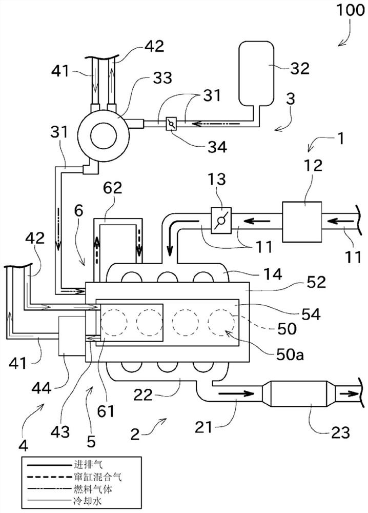
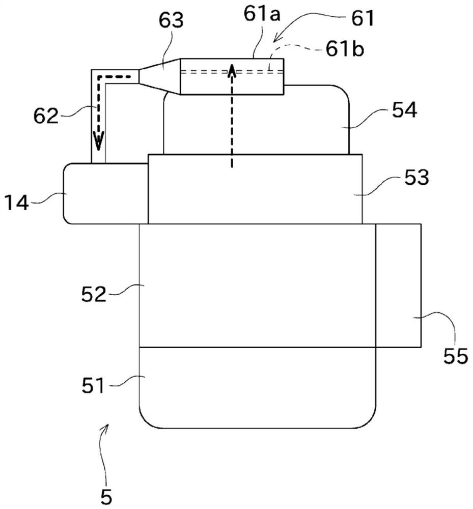
[0023] Next, embodiments of the present invention will be described with reference to the drawings. figure 1 It is a schematic diagram showing the flow of intake and exhaust gases, fuel gas, and the like in the engine 100 according to an embodiment of the present invention. figure 2 is a schematic diagram of the engine 100 .

[0024] figure 1 The illustrated engine 100 is a gas engine that generates power by combusting fuel gas such as petroleum gas and natural gas. In addition, the engine 100 may also be other internal combustion engines such as a gasoline engine or a diesel engine. The engine 100 is used, for example, as a power generator, a heat pump, or a drive source of a mobile body. Such as figure 1 , etc., the engine 100 is mainly composed of an intake unit 1 , an exhaust unit 2 , a fuel gas supply unit 3 , a cooling unit 4 , an engine main body 5 and a blow-by gas recirculation unit 6 .

[0025] The intake portion 1 takes in air from the outside. The intake uni...


PUM


Abstract

The invention relates to a breather device and an engine. The breather device separates engine oil included in a blow-by gas. The breather device comprises a first route (81), an acceleration route (82), a branching route (83), and turn-back routes (84). The blow-by gas flows to the first route (81). The acceleration route (82) is connected to a downstream side of the first route (81), and has a flow channel cross-sectional area smaller than that of the first route (81). The branching route (83) is connected to a downstream side of the acceleration route (82), configured including a wall partorthogonal to the acceleration route (82), and branched into two routes by the wall part. The turn-back routes (84) are connected to one route branching at the branching route (83), and are turned back so as to be parallel to the acceleration route (82) and to head in the opposite direction from a progressing direction.

Description

technical field [0001] The present invention mainly relates to a ventilation device for separating engine oil contained in blow-by gas. Background technique [0002] Patent Document 1 discloses a cylinder head cover having a function of separating oil contained in blow-by gas leaking from a combustion chamber. A gas flow path for discharging blow-by gas introduced from the cylinder head side to the outside is formed in the head cover. A high-pressure portion having a small cross-sectional area of ​​the gas flow path is formed in the gas flow path. By passing the blow-by gas through the high-pressure unit, the high-speed blow-by gas collides with the wall, thereby separating the oil contained in the blow-by gas. [0003] Patent Document 1: Japanese Patent Laid-Open No. 2017-150435 [0004] However, only the structure of Patent Document 1 cannot sufficiently separate the oil contained in the blow-by gas, and therefore improvement is desired. Contents of the invention [...

Claims


Application Information

Patent Timeline
Patent Type & Authority Applications(China)
IPC IPC(8): F01M13/04F01P3/12
CPCF01M13/04F01P3/12F01M2013/0433F01M2013/0461F01M13/0416F01M13/0011F01M2013/0044
Inventor 高松孝太杉本正人
Owner YANMAR POWER TECHNOLOGY CO LTD
Why Eureka
Try Eureka