Filler-saving two-stage gas treatment device

A processing device, gas technology, applied in the field of gas fixed bed processing device

Active Publication Date: 2021-01-05
SHANGHAI SHENCHENG ENVIRONMENTAL PROTECTION EQUIP ENG
View PDF19 Cites 2 Cited by
  • Summary
  • Abstract
  • Description
  • Claims
  • Application Information

AI Technical Summary

Problems solved by technology

[0002] Existing gas treatment devices are routinely used as single-stage treatment devices, and all packings are replaced as a whole after failure

Method used


Image

  • Filler-saving two-stage gas treatment device
  • Filler-saving two-stage gas treatment device
  • Filler-saving two-stage gas treatment device

Examples


Embodiment 1

[0014] Example 1 Two-stage adsorption device with independent adsorption unit

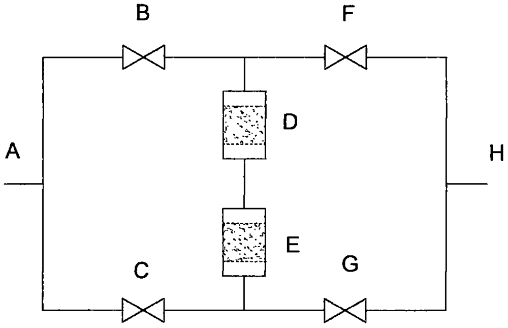
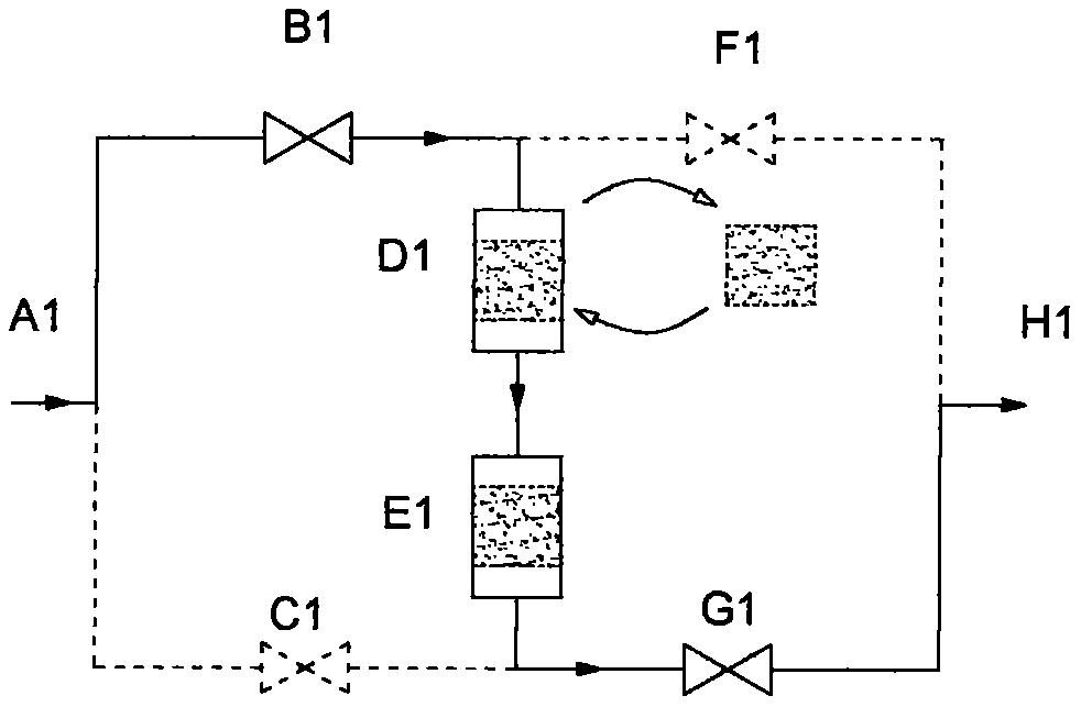
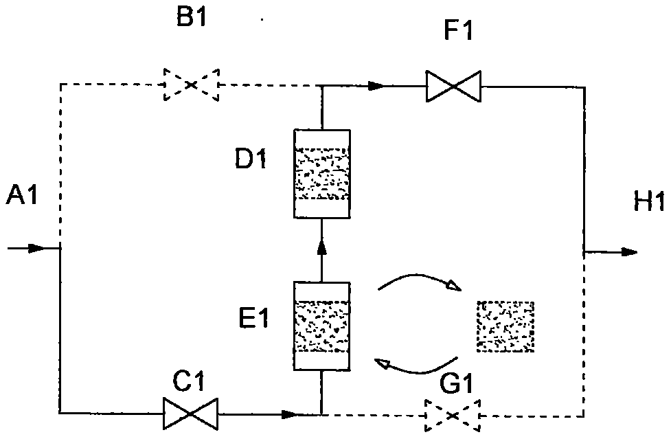
[0015] See attached Figure 2-3 . The device includes intake manifold A1, intake switching valve B1, intake switching valve C1, adsorption unit D1, adsorption unit E1, exhaust switching valve F1, exhaust switching valve G1 and exhaust manifold H1. The adsorption units D1 and 1E are equivalent to two independent fixed-bed adsorbers.

[0016] When the device works, it first works in the way 1) A1-B1-D1-E1-G1-H1, and the adsorbent in the adsorption unit D1 reaches saturation first, and the adsorption unit E1 has not penetrated yet. Replace the adsorbent in the adsorption unit D1, switch the gas passage to the mode 2) A1-C1-E1-D1-F1-H1, until the adsorbent in the adsorption unit E1 reaches saturation, then replace the adsorbent in the adsorption unit E1 , and switch the gas passage to mode 1), and so on.

Embodiment 2

[0017] Example 2 Compact matrix two-stage adsorption device

[0018] The adsorption units D1 and E1 in Example 1 are replaced by multiple parallel fixed beds I and J, and the gas pipeline connected between the two adsorption units is replaced by a grid plate K that divides the two adsorption sections. The gas sequence runs through the parallel fixed beds of the attached units D and E, and the valves B1, C1, E1, and F1 are set as two sets of linked switching valves L and M, and the adsorption device is transformed into a more practical compact matrix two-stage level adsorption device. The side-by-side fixed beds can be set as adsorbent drawers for easy replacement, which can further simplify the operation process of replacing the adsorbent. This knot structure can also greatly reduce the wind resistance of the device.

Embodiment 3

[0019] Example 3 Combination of compact matrix two-stage adsorption device and pre- and post-treatment processes

[0020] When the compact matrix two-stage adsorption device is used for VOCs gas removal and combined with pre- and post-processing devices such as dust filter N, and post-processing devices such as hydrogen sulfide catalytic oxidizer O, the advantages of compact device structure can be more reflected.


PUM


Abstract

The invention relates to a fixed bed treatment device. A single-stage treatment device is conventionally applied to an existing fixed bed treatment device, and all filler is integrally replaced afterpenetration. The invention discloses a series two-stage treatment device which comprises an air inlet main pipe A, an air inlet switching valve B, an air inlet switching valve C, an adsorption unit D,an adsorption unit E, an exhaust switching valve F, an exhaust switching valve G and an exhaust main pipe H, which form a treatment pipeline system similar to a Wheatstone bridge in shape. Gas has two passing ways, and fillers in the treatment units D and E can be independently replaced respectively. The device can fully utilize the treatment capacity of a treating agent, can ensure that the treatment bed is not penetrated, and ensures the purification efficiency of the treatment device. When the failed treating agent is replaced, only the failed treating agent needs to be replaced with a newor regenerated treating agent, and the gas passing path is changed through the control valve, so that the new treating stage is positioned at the position of second-stage treatment.

Description

technical field [0001] The invention relates to a gas fixed bed treatment device, and further relates to a gas adsorption purification device. Background technique [0002] The conventional application of the existing gas processing device is a single-stage processing device, and all the fillers are replaced as a whole after failure. Contents of the invention [0003] The invention discloses a two-stage gas treatment device connected in series, see attached figure 1 , including intake manifold A, intake switching valve B, intake switching valve C, processing unit D, processing unit E, exhaust switching valve F, exhaust switching valve G and exhaust manifold H. The above components form a set of gas processing passages in the shape of a Wheatstone bridge. The intake manifold A and the exhaust manifold H are equivalent to the two poles of the power supply, and the two intake switching valves B and C are equivalent to the two exhaust switching valves F and G. With 4 resisto...

Claims


Application Information

Patent Timeline
Patent Type & Authority Applications(China)
IPC IPC(8): B01D53/02B01D53/04B01D53/86
CPCB01D53/02B01D53/86B01D53/04
Inventor 吕建伟张传忠陈健
Owner SHANGHAI SHENCHENG ENVIRONMENTAL PROTECTION EQUIP ENG
Why Eureka
Try Eureka