Balance pier block height adjusting device
A height adjustment device and balancing technology, applied in metal processing equipment, forming tools, manufacturing tools, etc., can solve problems such as increasing the cost of parts, and achieve the effect of reducing cost input, facilitating separation, and reducing application
- Summary
- Abstract
- Description
- Claims
- Application Information
AI Technical Summary
Problems solved by technology
Method used
Image

Examples
Embodiment Construction
[0018] In order to facilitate the understanding of those skilled in the art, the present invention will be further described below in conjunction with the accompanying drawings.
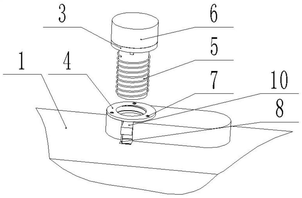
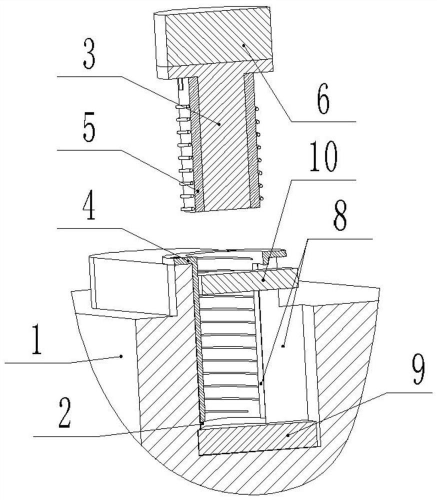
[0019] Such as Figure 1-2 The height adjustment device of a balance pier block shown includes a mounting hole 2 provided on the mold body 1, and a height-adjustable jacking block 3 is arranged in the mounting hole 2, and the jacking block 3 is far away from the mounting hole A gasket 6 is placed at one end of the 2, a set connection is provided between the mounting hole 2 and the top block 3, a first electromagnet 9 is fixedly installed on the inner bottom surface of the mounting hole 2, and the top block 3 is close to the One end of the mounting hole 2 is equipped with a second electromagnet 10 matched with the first electromagnet 9. The set includes an outer sleeve 4 and an inner sleeve 5, and the inner sleeve 5 and the outer sleeve 4 are made of non-magnetic materials. After the processing is co...
PUM
 Abstract
Description
Claims
Application Information
 - R&D
- Intellectual Property
- Life Sciences
- Materials
- Tech Scout
- Unparalleled Data Quality
- Higher Quality Content
- 60% Fewer Hallucinations
Browse by: Latest US Patents, China's latest patents, Technical Efficacy Thesaurus, Application Domain, Technology Topic, Popular Technical Reports.
© 2025 PatSnap. All rights reserved.Legal|Privacy policy|Modern Slavery Act Transparency Statement|Sitemap|About US| Contact US: help@patsnap.com