A control welding method for the shape and position deformation of the underframe floor of the EMU

A technology of deformation control and welding method, which is applied in the direction of welding equipment, manufacturing tools, metal processing equipment, etc., can solve the problem of difficult-to-repair floor profile cavity depressions and protrusions and lateral shrinkage, cumbersome welding procedures for chassis floors, and increased worker labor Intensity and other issues, to achieve the effect of eliminating size adjustments, eliminating repeated cutting, and reducing labor intensity

Active Publication Date: 2021-12-14
CRRC CHANGCHUN RAILWAY VEHICLES CO LTD
View PDF8 Cites 0 Cited by
  • Summary
  • Abstract
  • Description
  • Claims
  • Application Information

AI Technical Summary

Problems solved by technology

[0003] In order to solve the defects of cavity depression, protrusion and lateral shrinkage of the floor profile that are difficult to repair after welding the floor of the EMU chassis in the prior art, the product quality is reduced, and the labor intensity of the workers is not only increased during repairing , which makes the welding procedure of the chassis floor more cumbersome, reduces the production efficiency and prolongs the production cycle, and provides an EMU chassis floor shape that can repair the cavity depressions and protrusions and lateral shrinkage defects of the floor profile bit deformation control welding method

Method used


Image

  • A control welding method for the shape and position deformation of the underframe floor of the EMU
  • A control welding method for the shape and position deformation of the underframe floor of the EMU
  • A control welding method for the shape and position deformation of the underframe floor of the EMU

Examples


Embodiment Construction

[0021] The technical solutions of the present invention will be described in detail below in conjunction with the accompanying drawings and preferred embodiments.

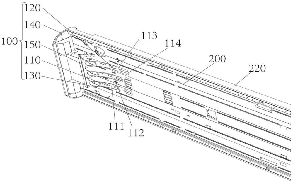
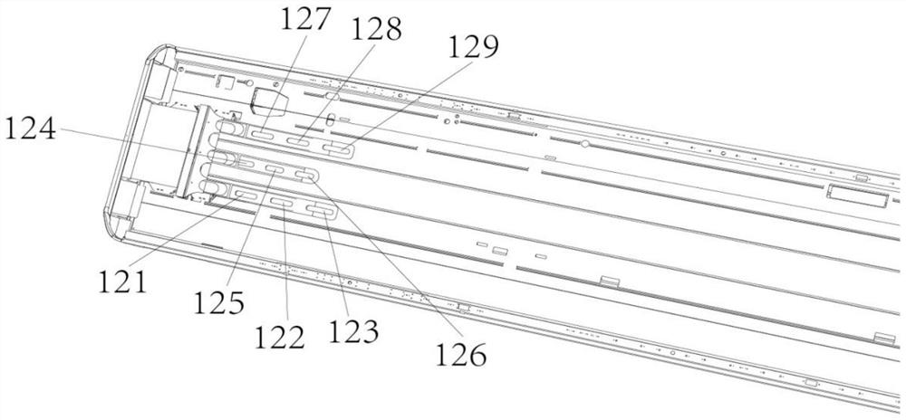
[0022] The invention provides a method for controlling the shape and position deformation of the underframe floor of an EMU that can repair the cavity depressions and protrusions of the floor profiles and the defects of lateral shrinkage. The method is suitable for the underframe floor of rail vehicles including EMUs. Welding, wherein the EMU underframe floor includes end beam plates 100 and floor profiles 200, such as figure 2 As shown, the end beam plate 100 includes a front wall panel 140 and a coupler panel 150 in addition to a fixing seat 130 and a plurality of connecting beams 110, and a plurality of connecting beams 110 are fixed on the fixing seat 130, and each connection The beam 110 is provided with a plurality of reinforcing holes 120'.

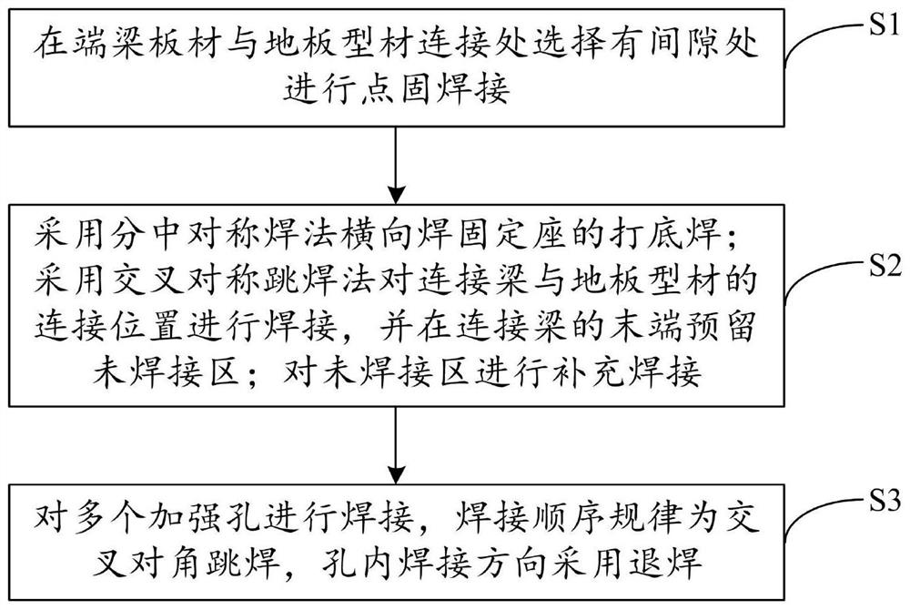
[0023] In one of the examples, as figure 1 As shown, the presen...


PUM

PropertyMeasurementUnit
lengthaaaaaaaaaa

Abstract

The invention relates to a welding method for shape and position deformation control of the underframe floor of an EMU, comprising the following steps: selecting a place with a gap between the end beam plate and the floor profile to perform spot welding, and the end beam plate includes a fixing seat and several connecting beams , each connecting beam is provided with a plurality of reinforcement holes; the bottom welding of the fixed seat is welded horizontally by the split symmetrical welding method, and the connecting position of the connecting beam and the floor profile is welded by the cross symmetrical jump welding method, and the connecting beam is welded on the connecting beam. Reserve the unwelded area at the end of the hole, and then perform supplementary welding on the unwelded area; weld multiple reinforced holes, the welding sequence is cross-diagonal jump welding, and the welding direction in the hole is reversed. The invention improves product quality, ensures that the floor of the underframe of the EMU is flat and not deformed after welding; improves production efficiency, prevents size adjustment after welding, and effectively guarantees the production cycle; reduces labor intensity, and prevents repeated cutting after welding , so that the entire welding procedure becomes simplified and easy to operate.

Description

technical field [0001] The invention relates to the technical field of EMU manufacturing, in particular to a method for controlling the shape and position deformation of the underframe floor of an EMU. Background technique [0002] The floor of the EMU underframe includes an end beam plate and a floor profile, specifically, the end beam plate includes a connecting beam, and the floor profile includes a cavity. There is a large thickness difference between the end beam plate and the floor profile (the thickness of the end beam plate is 15mm, and the thickness of the floor profile is 4mm), and the cavities of the floor profile are distributed in the welding position with the end beam plate. Due to the long welding seam, the concentrated number of welding seams, the large heat input during welding, the uneven temperature distribution, and the uneven cooling and heat dissipation of thin and thick plates, it is easy to cause the cavity depression of the floor profile that is diff...

Claims


Application Information

Patent Timeline
Patent Type & Authority Patents(China)
IPC IPC(8): B23K31/00B23K31/02
CPCB23K31/00B23K31/02
Inventor 周晶辉臧铁军聂洪刚
Owner CRRC CHANGCHUN RAILWAY VEHICLES CO LTD
Why Eureka
Try Eureka