
Packing device for annular steel bars

A technology of ring-shaped steel bars and pressure devices, which is applied in the direction of packaging and binding machine parts, etc., can solve problems such as insufficient efficiency, and achieve the effect of improving efficiency and solving insufficient efficiency

Pending Publication Date: 2021-01-05
射洪县才伦建材有限责任公司
View PDF1 Cites 1 Cited by
  • Summary
  • Abstract
  • Description
  • Claims
  • Application Information

AI Technical Summary

Problems solved by technology

[0004] The purpose of the present invention is to provide a packaging device for circular steel bars, by setting the connecting components, the separation and connection of the fixed column and the connecting column are facilitated, and then the placing device on the first column can be conveniently and quickly The U-shaped binding wire is moved to the top of the spiral-shaped steel bar group, which improves the efficiency of bundling and packing, and solves the problem of insufficient bundling and packing efficiency of the original packing equipment.

Method used


Image

  • Packing device for annular steel bars
  • Packing device for annular steel bars
  • Packing device for annular steel bars

Examples


Embodiment 1

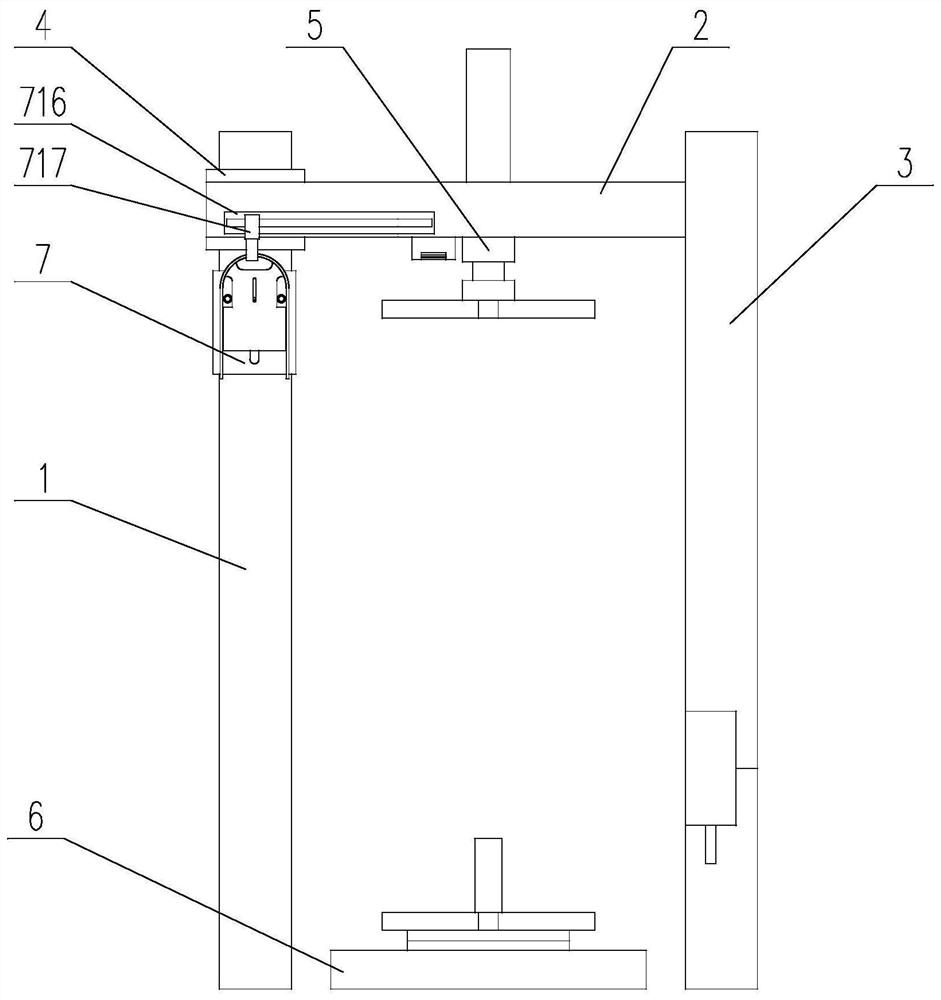
[0039] A packaging device for circular steel bars, comprising a gantry device and a placing device 7, the gantry device includes a gantry body, a fixing device 6 and a pressure device 5, and the gantry body includes a first column 1 and a beam 2 And the second column 3, the top of the first column 1 is connected with one end of the beam through the rotating device 4, the other end of the beam 2 is connected with the top of the second column 3, the fixing device 6 is installed on the ground, And located between the first column 1 and the second column 3, the pressure device 5 is connected to the bottom surface of the beam 2;

[0040] The second column 3 includes a connecting column 302 and a fixed column 301, the connecting column 302 is connected with the fixed column 301 installed on the ground through a connecting assembly, and the connecting assembly includes a fixed plate 303, a connecting plate 305, and a movable plate 304 , limiting plate 306, movable block 307, mating b...

Embodiment 2

[0046] A specific implementation description is made for the operation mode in Embodiment 1.

[0047] like Figure 5 As shown, in the present invention, a push rod 317 is connected to the side of the movable block 307 away from the fixed post 301. The push rod 317 is a better point of application of force, and the user can better push the movable block 307 by the push rod 317. The surface of the rod 317 is provided with anti-skid lines, which can increase the frictional force and prevent hands from being released when the push rod 317 is gripped tightly to apply force.


PUM


Abstract

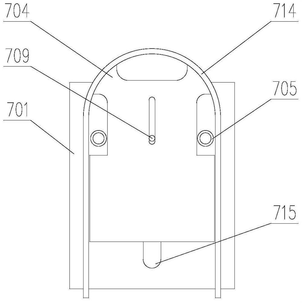
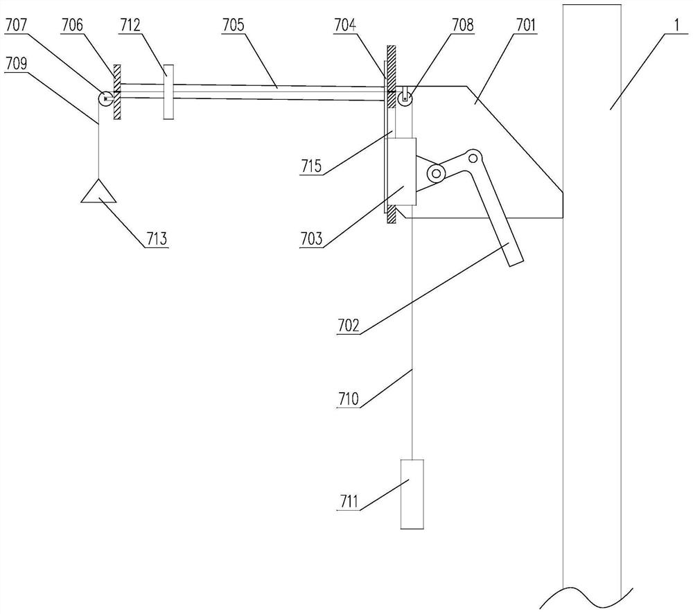
The invention discloses a packing device for annular steel bars. The packing device comprises a portal frame device and a placing device, a second stand column comprises a connecting column and a fixing column, the connecting column is connected with the fixing column installed on the ground through a connecting assembly, and the placing device is installed on a first stand column; the placing device comprises a fixing frame, a transmission mechanism, a connecting block, a push plate, a guide rod, a mounting plate, a pulley A, a pulley B, a connecting rope A, a connecting rope B, a gravity block, a guide rail and a clamping jaw, the connecting rope A sequentially penetrates through the pulley A, the mounting plate, the push plate, the fixing frame and the pulley B and then is connected with the top of the connecting block; and one end of the connecting rope B is connected with the bottom of the connecting block, and the other end of the connecting rope B is connected with the gravity block. The guide rail is installed on the side face of a cross beam, the top end of the clamping jaw is slidably connected with the guide rail, and the problem that the binding and packaging efficiencyof original packaging equipment is insufficient is solved.

Description

technical field [0001] The invention relates to the field of steel bar packing equipment, in particular to a packing device for circular steel bars. Background technique [0002] Cold-rolled ribbed steel bar is a new type of construction steel product that developed rapidly at home and abroad in the late 20th century. Cold-rolled ribbed steel bar has the advantages of high strength, good plasticity, and easy processing, and is a resource-saving product. Steel bar processing generally goes through the following processes: steel bar straightening, steel bar dephosphorization, steel bar rough rolling, steel bar finishing rolling, steel bar heat treatment, steel bar cutting, and steel bar packing. Rebar is packed in order to compress its volume, making it easier to transport. [0003] The prior art publication number is CN209097083U, a high-strength cold-rolled ribbed steel bar spiral pressure packer, by setting various corresponding mechanisms on the gantry, a large number of...

Claims


Application Information

Patent Timeline
IPC IPC(8): B65B13/28B65B13/18B65B27/06
CPCB65B13/18B65B13/28B65B27/06
Inventor 于宗菊傅华林
Owner 射洪县才伦建材有限责任公司
Learn More