Belt assembly line for workshop assembly
An assembly line and belt technology, applied in the field of assembly line, can solve the problems of lack of quick replacement and disassembly operations, complex alternating axial movement of side bearing belts, and poor mobility of the belt assembly line, so as to improve single linkage and enhance interspersed rotation Effects, Enhanced Smoothness, and Anti-Offset Effects
- Summary
- Abstract
- Description
- Claims
- Application Information
AI Technical Summary
Problems solved by technology
Method used
Image

Examples
Embodiment 1
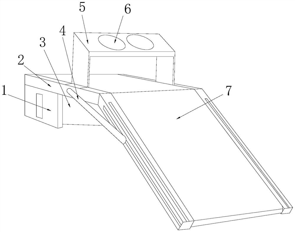
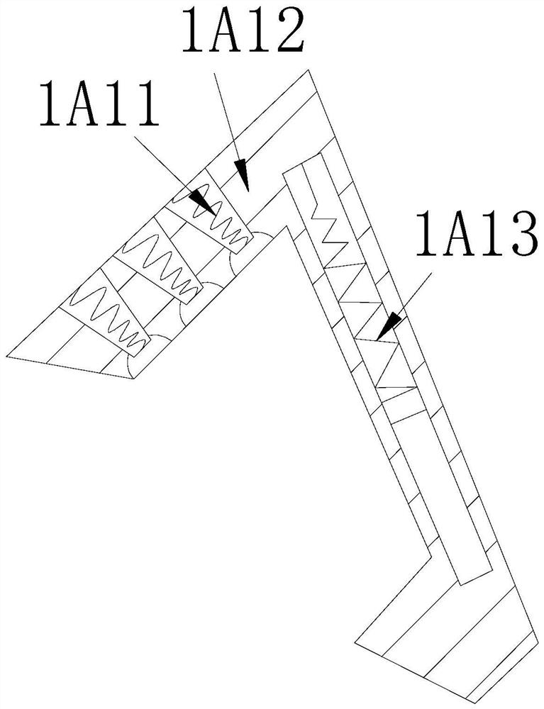
[0033] see Figure 1-Figure 6, the present invention provides a workshop assembly belt assembly line, the structure of which includes: roller support bar ring groove 1, platform frame plate 2, shaft motor 3, pull buckle strip 4, material retaining frame 5, propeller heat sink 6, Inclined belt 7, the roller bracket ring groove 1 is nested on the front side of the shaft motor 3, the platform frame plate 2 is installed on the top of the shaft motor 3, the material retaining frame 5 and the propeller dissipate heat The discs 6 are nested into one body, the material retaining frame 5 is inserted on the top surface of the platform frame plate 2 and is perpendicular to each other, the inclined belt 7 is mechanically connected with the platform frame plate 2 through the buckle strip 4, and the roller The support rod ring groove 1 is mechanically connected with the inclined belt 7 through the shaft rod, and the roller support rod ring groove 1 is provided with a support shaft ring disk...
Embodiment 2
[0040] see Figure 1-Figure 6 , the present invention provides a workshop assembly belt assembly line, other aspects are the same as embodiment 1, the difference is:
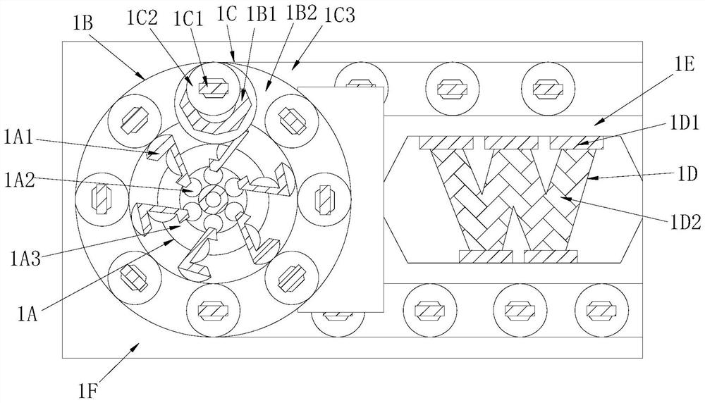
[0041] see figure 2 , the horizontal board support 1D is composed of a horizontal board 1D1 and a folding frame vertical board 1D2. The horizontal board 1D1 is provided with more than two and is respectively nested on the upper and lower sides of the folding frame vertical board 1D2. 1D1 presses and sticks the vertical plate of the folding frame up and down 1D2 to form the parallel correction operation effect of the high and low horizontal planes and inclined planes, ensuring the smoothness of assembly and processing in the belt assembly line workshop.
[0042] see Figure 6 , the horizontal patch plate 1D1 is composed of a horizontal plate groove 1D11, a patch plate 1D12, a buckle lug plate 1D13, and a shaft center wheel 1D14, and the patch plate 1D12 is mechanically connected to the shaft center wheel 1D14 ...
PUM
 Abstract
Description
Claims
Application Information