Quick-release intercepting device for ecological environment protection

An environmental protection and interception device technology, applied in water conservancy projects, open water surface cleaning, construction and other directions, can solve problems such as low efficiency of cleaning, damage to the ecological environment at the bottom of the river, and achieve low cost, increase the survival rate of aquaculture, The effect of reducing input costs

Inactive Publication Date: 2021-01-05
王浩潮
View PDF10 Cites 0 Cited by
  • Summary
  • Abstract
  • Description
  • Claims
  • Application Information

AI Technical Summary

Problems solved by technology

[0004] Manual salvage needs to rely on salvage boats, but the movement of salvage boats will generate waves and push the garbage outward, so the cleaning efficiency is low
[0005] Regular river dredging will destroy the ecological environment at the bottom of the river, and the silt contains more nutrients. Although cleaning the silt alone can effectively reduce the amount of garbage, the disadvantages outweigh the advantages

Method used


Image

  • Quick-release intercepting device for ecological environment protection
  • Quick-release intercepting device for ecological environment protection
  • Quick-release intercepting device for ecological environment protection

Examples


Embodiment 1

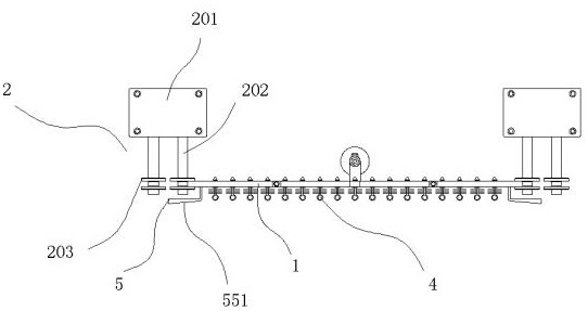
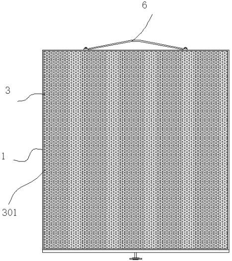
[0043] A quick-release intercepting device for ecological environment protection, including multiple baffles 1 installed at the front of the bridge, the baffles 1 are made of aluminum alloy or stainless steel, the wall thickness is 2mm, the width of the baffles 1 is 80cm, and the height is according to The depth of the water area is customized, and the height needs to be greater than the maximum water level in previous years; and the sliding support device 2 connected to the bridge and arranged on both sides of each baffle 1; the function of the sliding support device 2 is to reduce the sliding of the baffle 1 up and down The resistance at the time; the baffle 1 can slide vertically along the sliding support device 2; the inner side of the baffle 1 is hollow, and a thin plate 3 is welded on the inner side of the baffle 1, and the thin plate 3 is made of stainless steel material, the thickness is 1.2mm; the surface of the thin plate 3 is evenly distributed with water holes 301, ...

Embodiment 2

[0049] The catching device 4 includes an insertion shaft 401, and a rubber stopper 402 is mounted on the rear end of the insertion shaft 401. The stopper 402 has a tapered insertion surface 403, and the insertion surface 403 squeezes After being deformed, it passes through the water hole 301, and then rebounds to form a limit at the rear end of the thin plate 3; a retaining ring 404 is provided on the outer wall of the insertion shaft 401; the baffle plate 404 is limited at the The front part of the thin plate 3; a threaded part 405 is processed at the front end of the insertion shaft 401, and an extension shaft 406 is matched with the threaded part 405, and steel wire bristles 407 are evenly distributed on the outer wall of the extension shaft 406, and the The front portion of the extension shaft 406 is processed with a pull ring 408; the capture device 4 installed on the thin plate 3, the length of the extension shaft 406 gradually increases from top to bottom; the length of ...

Embodiment 3

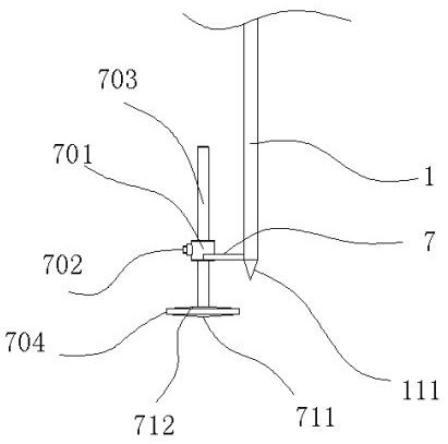
[0051] The lower end of the baffle 1 is processed to form a V-shaped insertion part 111. When the baffle 1 is inserted into the river bed, the V-shaped insertion part 111 is inserted into the river bed, and when the baffle 1 goes down the river, When inserting, the V-shaped inserting portion 111 reduces the river water resistance when inserting downward; the V-shaped inserting portion 111 can be inserted into the river bed more easily. If the V-shaped inserting portion 111 is not provided, the baffle plate 1 is only supported by the pulley. It will lead to poor stability of the lower end of the baffle plate 1 . And after adopting the V-shaped insertion portion 111, the lower end of the baffle plate 1 can be connected with the river bed.


PUM


Abstract

The invention discloses a quick-release intercepting device for ecological environment protection. The quick-release intercepting device comprises a plurality of baffles installed on the front portionof a bridge and sliding supporting devices connected to the bridge and arranged on the two sides of each baffle; the baffles can vertically slide along the sliding supporting devices; and the inner sides of the baffles are hollow, thin plates are welded to the inner sides of the baffles, water through holes are evenly distributed in the surfaces of the thin plates, catching devices are detachablyinstalled in the water through holes, and two side baffles are arranged at the front end of each baffle in a bilateral symmetry mode. According to the device, the baffles can slide up and down, whenemergency navigation is needed, the baffles can be opened upwards, and when the baffles are kept inserted, the baffles can intercept the water surface, circulation of water is not affected, and only garbage floating in water is intercepted.

Description

technical field [0001] The invention relates to a quick-release intercepting device for ecological environment protection. Background technique [0002] The bridge is a traffic infrastructure built on the water surface; we found in the actual investigation that there will be a lot of garbage floating in the river. The environment has deteriorated. [0003] In response to this situation, there are two existing treatment methods, the first is manual salvage of garbage, and the second is regular dredging of the river. [0004] Manual salvage needs to rely on salvage boats, but the movement of salvage boats will generate waves and push the garbage outward, so the cleaning efficiency is low. [0005] Regular river dredging will destroy the ecological environment at the bottom of the river, and the silt contains more nutrients. Although cleaning the silt alone can effectively reduce the amount of garbage, the disadvantages outweigh the benefits. [0006] To this end, we have de...

Claims


Application Information

Patent Timeline
Patent Type & Authority Applications(China)
IPC IPC(8): E02B15/08
CPCE02B15/08
Inventor 不公告发明人
Owner 王浩潮
Why Eureka
Try Eureka