High-strength damp-proof composite board

A composite board, high-strength technology, applied in the direction of sheet/board, thin board connection, connecting components, etc., can solve the problems of the failure of the moisture-proof material of the interlayer, and the moisture-proof composite board does not have the moisture-proof function, and achieves ingenious structure, improved strength, and extended use. effect of life

Inactive Publication Date: 2021-01-05
高嘉炜
View PDF0 Cites 0 Cited by
  • Summary
  • Abstract
  • Description
  • Claims
  • Application Information

AI Technical Summary

Problems solved by technology

[0003] The purpose of the present invention is to provide a high-strength moisture-proof composite board, which aims to solve the problem that some composite boards with moisture-proof function in the prior art are mostly realized by

Method used


Image

  • High-strength damp-proof composite board
  • High-strength damp-proof composite board
  • High-strength damp-proof composite board

Examples


Embodiment 1

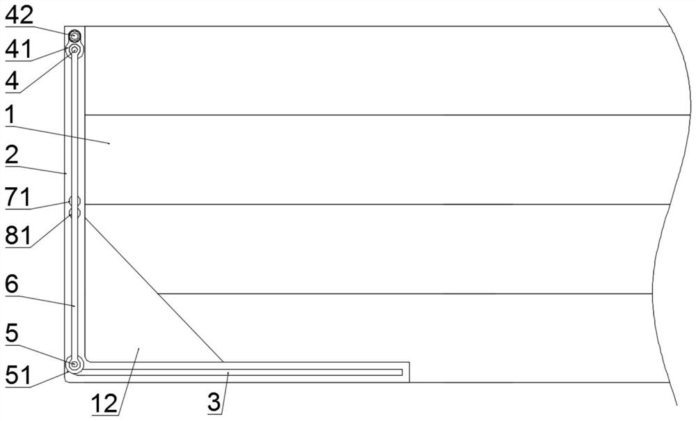
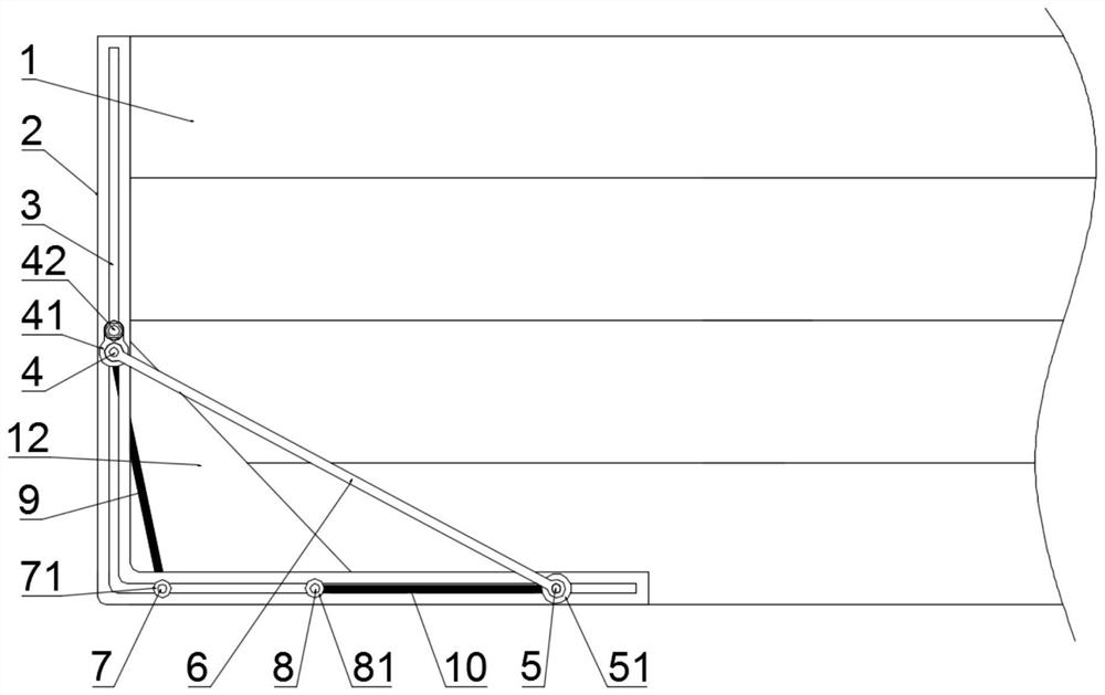
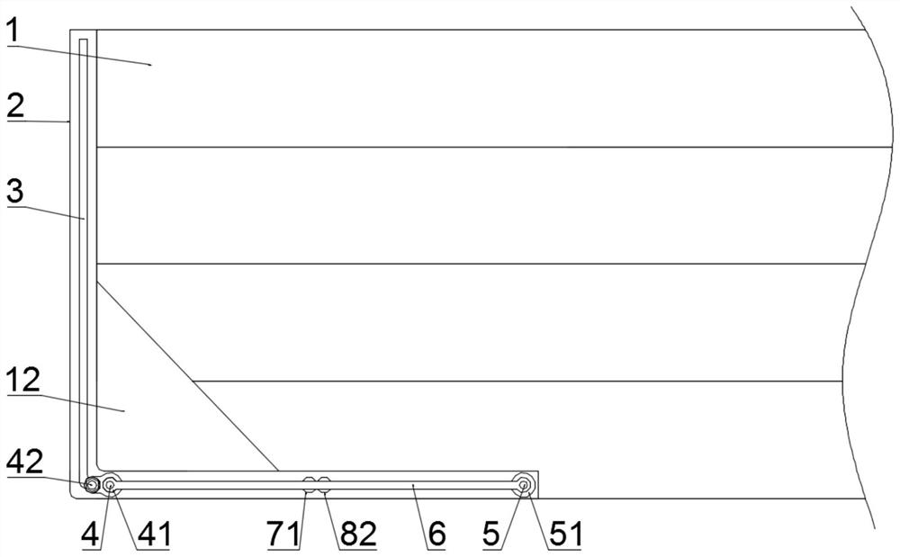
[0032] like Figure 1-6 As shown, a high-strength moisture-proof composite panel includes a composite panel body 1 and a right-angle frame 2, and the right-angle frame 2 is attached to the front side and the rear side of the end of the composite panel body 1, and is located between the front side and the rear side. The two right-angle frames 2 on the rear side are fixedly connected to each other through the fixing member 201. The right-angle frame 2 is provided with a right-angle through groove 3, and the right-angle through groove 3 is provided in order to slide along the right-angle through groove 3. The first slide bar 4, the second slide bar 7, the third slide bar 8 and the fourth slide bar 5 are moved, and a connecting rod 6 is arranged between the first slide bar 4 and the fourth slide bar 5. The two ends of the rod 6 are respectively hinged with the first sliding rod 4 and the fourth sliding rod 5, and the first baffle plate 9 is fixedly connected between the first slid...

Embodiment 2

[0039] like Figure 7 and 8 As shown, on the basis of Example 1, the right-angled frame 2 located on the different composite sheet bodies 1 is provided with snap-in mechanisms that are quickly connected to each other. Specifically, the snap-in mechanisms include fixedly arranged The fixed block 13 at the bottom of the right-angle frame 2, the fixed block 13 is provided with a through hole 14, and the upper part of the right-angle frame 2 is fixedly provided with a fixed cross bar 15, and the fixed cross bar 15 passes through a mobile plate 16 to move The plate 16 is connected to the surface of the right-angle frame 2 through a first spring 18, and the other end of the fixed cross bar 15 is fixedly connected with a protrusion 19 for preventing the moving plate 16 from breaking away from the fixed cross bar 15. The upper part of the moving plate 16 is formed with a limiting block 17 that can pass through the through hole 14 . The limiting block 17 is in the shape of a flat side...

Embodiment 3

[0042] like Figure 9 and 10 As shown, on the basis of Example 2, the right-angle frame 2 is provided with a plug-in device for inserting into the composite panel body 1 to increase the firmness of the connection with the composite panel body 1, specifically, the The plug-in device includes a vertical rod 20 fixedly arranged on the right-angle frame 2 in a vertical direction, and the vertical rod 20 is hinged with a protruding thorn 22 arranged obliquely downward, and the protruding thorn 22 is connected with the second spring 22 to The uprights 20 are connected.

[0043] When the composite panel body 1 needs to be installed on the right-angle frame 2, the composite panel body 1 can be directly pressed down to fit the right-angle frame 2. The setting can effectively prevent the separation of the composite board body 1 and the right-angle frame 2, and make the connection between the two firm.

[0044] Preferably, both the top end of the upright rod 20 and the inclined lower ...


PUM


Abstract

The invention provides a high-strength moisture-proof composite board, and relates to the technical field of boards. The high-strength moisture-proof composite board comprises a composite board body and right-angle frames, wherein the right-angle frames are attached to the front side surface and the rear side surface of the end part of the composite board body; and the two right-angle frames located on the front side face and the rear side face are fixedly connected with each other through fixing parts, right-angle through grooves are formed in the right-angle frames, and a first sliding rod,a second sliding rod, a third sliding rod and a fourth sliding rod which can slide along each right-angle through groove are sequentially arranged in each right-angle through groove. According to thehigh-strength moisture-proof composite board, when drying agents lose efficacy after long-time use, all first baffles and second baffles can be moved to one side again, and at the moment, all the drying agents located in containing grooves of the composite board body fall out, and a new drying agent is reloaded, so that replacement of the drying agent is achieved, it is guaranteed that the composite board body can have a damp-proof function all the time, and the service life of the composite board body is prolonged.

Description

technical field [0001] The invention relates to the technical field of plates, in particular to a high-strength moisture-proof composite plate. Background technique [0002] Composite board refers to a board made of two or more materials. For boards of different materials, the concept and production method of composite boards are also different. Some composite boards with moisture-proof function are mostly made of interlayer moisture-proof materials. However, after a long time of use, the moisture-proof material of the interlayer will fail, and the moisture-proof composite board will not have the moisture-proof function. Contents of the invention [0003] The purpose of the present invention is to provide a high-strength moisture-proof composite board, which aims to solve the problem that some composite boards with moisture-proof function in the prior art are mostly realized by interlayer moisture-proof materials, but after long-term use, the interlayer moisture-proof mate...

Claims


Application Information

Patent Timeline
IPC IPC(8): F16S1/10F16S1/02F16S1/14F16B5/10F16B5/00B01D53/26
CPCB01D53/26F16B5/0004F16B5/10F16S1/02F16S1/10F16S1/14
Inventor 高嘉炜
Owner 高嘉炜
Why Eureka
Try Eureka