Unlock instant, AI-driven research and patent intelligence for your innovation.

Intelligent LED lamp

A kind of LED lamp, intelligent technology, applied in the direction of building type, lighting application, lighting and heating equipment, etc., can solve the problems such as poor contact between lamp beads and lamp holders, affecting the normal light emission of LED lamps, oxidation of metal guide strips of lamp holders, etc. Achieve the effects of accelerating water evaporation, reducing oxidation, and accelerating wind power

Inactive Publication Date: 2021-01-05
常州菲尼霖建筑装潢有限公司
View PDF0 Cites 2 Cited by
  • Summary
  • Abstract
  • Description
  • Claims
  • Application Information

AI Technical Summary

Problems solved by technology

[0003] In order to solve the above-mentioned technology, when the LED lamp is installed inside the mine, due to the humid air inside the mine, when the minerals are mined in the machine, the internal air flow speed is accelerated, and the air enters the inside of the lamp body from the heat dissipation hole, causing the lamp The metal guide strips around the seat are oxidized, which is prone to poor contact between the lamp bead and the lamp seat, which affects the normal light emission of the LED lamp. The invention provides an intelligent LED lamp

Method used


Image

  • Intelligent LED lamp
  • Intelligent LED lamp
  • Intelligent LED lamp

Examples


Embodiment 1

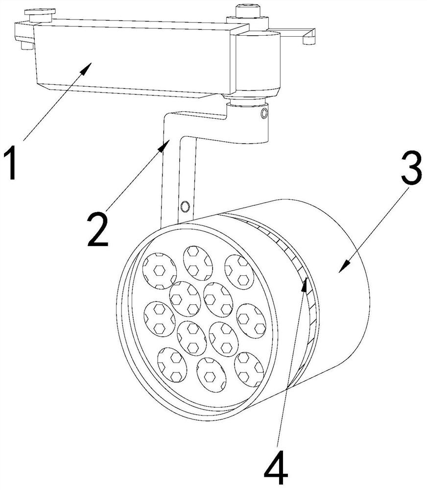
[0025] as attached figure 1 To attach Figure 5 Shown:

[0026] The invention provides an intelligent LED lamp, the structure of which includes a controller 1, a bracket 2, a lamp body 3, and a cooling hole 4. The bracket 2 is installed on the lower side of the right end of the controller 1. The heat dissipation holes 4 are arranged in the middle of the lamp body 3 .

[0027] The lamp body 3 is provided with a lamp holder 31, a lamp bead 32, a wire 33, and a side block 34. The lamp holder 31 is installed in the middle of the lamp body 3, the lamp bead 32 is located on the left side of the lamp holder 31, and the wire 33 is located on the right side of the lamp holder 31, and the side block 34 is fixed on the inner middle of the right side of the lamp body 3.

[0028] Wherein, the side block 34 is provided with a magnetic block a1, a support rod a2, an impeller a3, a removal rod a4, and an air hole a5, and the magnetic block a1 is fixed on the right side inside the side bloc...

Embodiment 2

[0034] as attached Figure 6 To attach Figure 7 Shown:

[0035] Wherein, the removal rod a4 is provided with a removal block r1, a collection tank r2, a spring r3, and a connection block r4, the removal block r1 is located on the upper and lower sides of the removal rod a4, and the collection tank r2 is arranged inside the removal rod a4, so The spring r3 is clamped on the inner wall on the right side of the cleaning block r1, and the connecting block r4 is connected to the inner wall at the right end of the cleaning block r1. The connecting block r4 is made of rubber material and has elasticity, which is beneficial to drive the cleaning block r1 to vibrate up and down to speed up the removal of dust Sliding down, the surface of the removal block r1 is in a concave shape, which is beneficial to increase the contact area with the outer wall of the impeller a3 and speed up the removal of dust on the outer wall of the impeller a3.

[0036] Wherein, the cleaning block r1 is pro...


PUM


Abstract

The invention discloses an intelligent LED lamp which structurally comprises a controller, a support, a lamp body and heat dissipation holes, the support is installed on the lower side of the right end of the controller, the lamp body is connected with the tail end of the support; and due to the fact that air in a mine is humid and metal guide pieces around a lamp holder are oxidized, a phenomenonthat lamp beads make poor contact with the lamp holder is likely to happen. Blades of an impeller have magnetism and rotate in cooperation with a magnetic rod to generate wind power, evaporation of water around a lamp holder is accelerated, oxidation of metal blocks of the lamp holder is reduced, tight contact between lamp beads and the lamp holder is facilitated, normal light emitting of an LEDlamp and illumination of the interior of a mine are achieved, and due to the fact that dust contained in air is easily accumulated on the outer wall of the impeller, the gravity of the impeller is increased; and when the rotating speed of the impeller is changed, dust on the outer wall of the impeller is removed through movable matching of a removing block of a removing rod and the outer wall of the impeller, the bearing force of the impeller is better relieved, the rotating frequency of the impeller is increased, wind power generated by the impeller is accelerated, and evaporation of water around the lamp holder is accelerated.

Description

technical field [0001] The invention belongs to the field of LED lamps, and more specifically relates to an intelligent LED lamp. Background technique [0002] LED lamps have high light intensity and low power consumption. LED lamps are widely used in various fields. LED lamps are equipped with induction devices to automatically control the power on and off of lamp beads. Due to insufficient lighting conditions inside the mine, LED lamps are installed in Mine interior lighting, LED lights generate heat during the long-term luminous process, and LED lights are provided with cooling holes to speed up heat dissipation; in the prior art, when LED lights are installed inside the mine, due to the humid air inside the mine, when minerals are mined in the machine During the process, the internal air flow speed is accelerated, and the air enters the interior of the lamp body from the heat dissipation hole, causing the metal guides around the lamp holder to be oxidized, and poor conta...

Claims


Application Information

Patent Timeline
IPC IPC(8): F21S8/00F21V23/00F21V31/00F21V33/00B08B1/04F26B21/00F21Y115/10F21W131/402
CPCF21S8/00F21V23/00F21V31/00F21V33/0096F26B21/004F21Y2115/10F21W2131/402B08B1/32
Inventor 王晓明
Owner 常州菲尼霖建筑装潢有限公司