Current transmission device for motor, motor with current transmission device and vehicle

A transmission device and current technology, applied in the fields of motors and vehicles, can solve the problems of large overall structure and easy external influence, and achieve the effect of avoiding influence, compact and reliable conductive fluid transmission structure

Pending Publication Date: 2021-01-05
FORD GLOBAL TECH LLC
View PDF1 Cites 0 Cited by
  • Summary
  • Abstract
  • Description
  • Claims
  • Application Information

AI Technical Summary

Problems solved by technology

In this structure, the rotating good conductor device, the stationary good conductor device and the good conductor liquid are all arranged outside the generator shaft, and the overall structure is large and susceptible to external influences

Method used

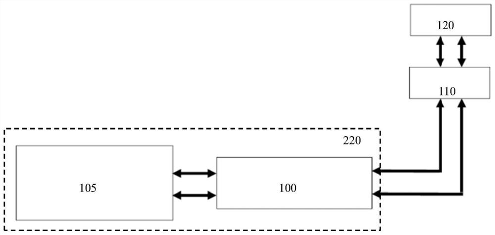
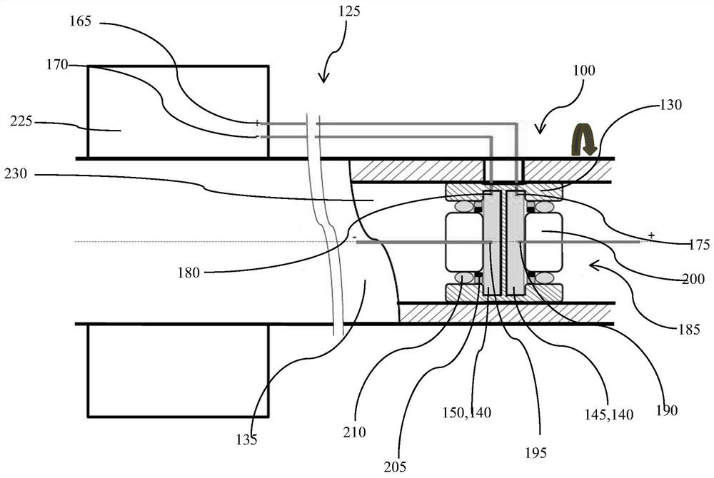
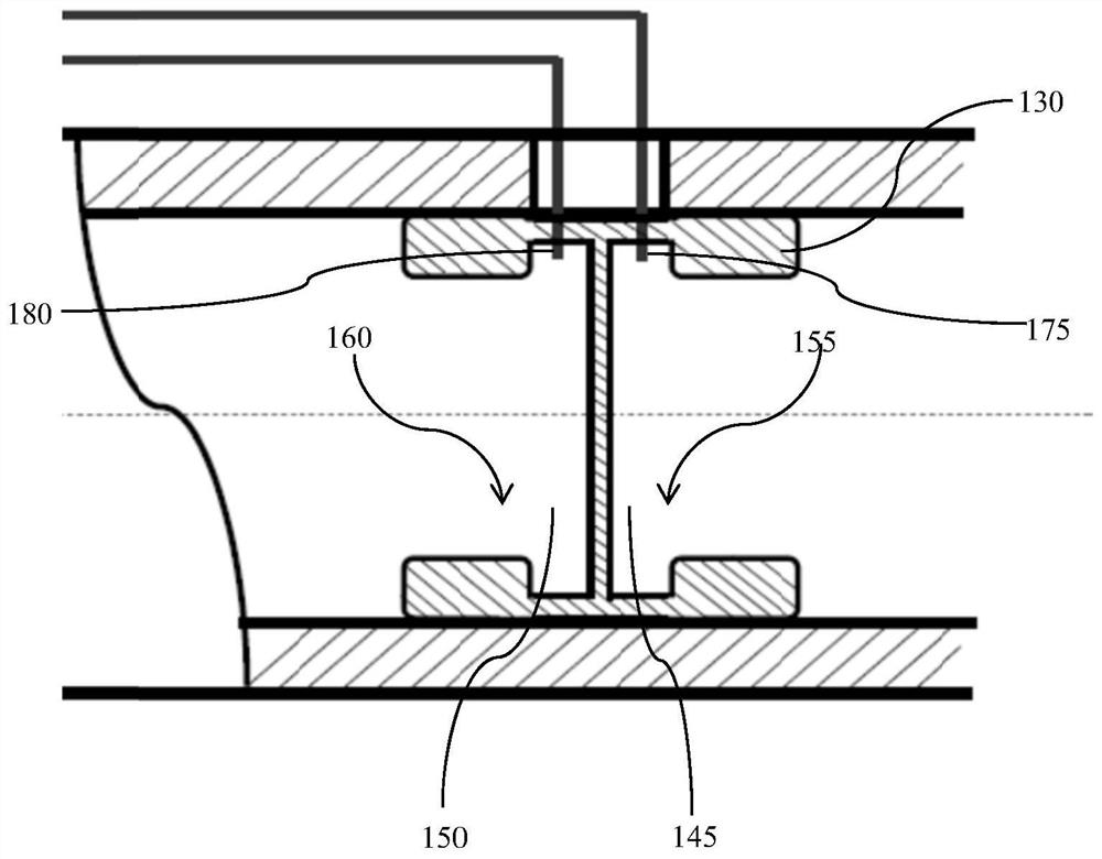

Image

  • Current transmission device for motor, motor with current transmission device and vehicle
  • Current transmission device for motor, motor with current transmission device and vehicle
  • Current transmission device for motor, motor with current transmission device and vehicle

Examples


Embodiment Construction

[0048] Embodiments of the present disclosure are described below. It is to be understood, however, that the disclosed embodiments are merely examples and that other embodiments may take various alternative forms. The figures are not necessarily to scale; some features may be exaggerated or minimized to show details of particular components. Therefore, specific structural and functional details disclosed herein are not to be interpreted as limiting, but merely as a representative basis for teaching one skilled in the art to variously employ the present invention. As will be understood by persons of ordinary skill in the art, various features shown and described with reference to any one figure can be combined with features shown in one or more other figures to create embodiments not explicitly shown or described . Combinations of features shown provide representative embodiments for typical applications. However, various combinations and modifications of the features consist...


PUM


Abstract

According to the present invention, there is provided a current transmission device for a motor, the device including: a rotating bearing member fixed in a rotor shaft and rotating therewith, and a non-rotating member. The rotary bearing member includes: a first compartment filled with a conductive fluid, having a first opening, and a rotor anode connector in electrical contact with the conductivefluid therein and electrically connected to a rotor positive electrode; and a second compartment filled with a conductive fluid and insulated from the first compartment, having a second opening, anda rotor negative electrode connector in electrical contact with the conductive fluid therein and electrically connected to the rotor negative electrode. The non-rotating member closes the first and second openings and includes: a power supply positive electrode connecting piece extending into the first compartment and in electrical contact with the conductive fluid therein; and a power supply negative electrode connecting piece extending into the second compartment and in electric contact with the conductive fluid in the second compartment. Compared with an existing conductive fluid transmission structure, the device is integrated in the rotor shaft, is more compact and reliable, and is prevented from being affected by the outside to the maximum extent.

Description

technical field [0001] The present invention generally relates to the field of electric technology, and in particular, relates to a current transmission device for a motor, a motor and a vehicle with the device. Background technique [0002] Current motors generally include two parts, a rotor and a stator, as an energy conversion device for converting electrical energy into mechanical energy and converting mechanical energy into electrical energy. In some motor structures, it is necessary to transmit DC power through the power supply to the rotor winding of the motor rotor or in the opposite direction to generate an electric field, which in turn can make the rotor rotate with the rotating magnetic field of the motor stator. [0003] The process of transmitting direct current from the power supply to the rotor winding of the motor rotor or in the reverse direction involves the current transmission between moving parts. At present, the main technical solutions used in this fie...

Claims


Application Information

Patent Timeline
Patent Type & Authority Applications(China)
IPC IPC(8): H02K13/00H01R3/08
CPCH02K13/00H01R3/08H01R2201/26H01R2201/10H02K13/003H01R39/10H01R39/646
Inventor 邓钏杜国华袁怡刚
Owner FORD GLOBAL TECH LLC
Why Eureka
Try Eureka