Rotor Coupling Center Alignment Disk Device for Turbine Generator Set

A technology for turbogenerator sets and disk drives, applied to shaft couplings, rigid shaft couplings, mechanical equipment, etc., can solve the problems of excessive rotor disk motion, repeated disk rework, heavy rotor weight, etc., and achieve Overcome the influence of external force and ensure the effect of consistent position

Active Publication Date: 2016-03-02
POWERCHINA SEPCO1 ELECTRIC POWER CONSTR CO LTD
View PDF7 Cites 0 Cited by
  • Summary
  • Abstract
  • Description
  • Claims
  • Application Information

AI Technical Summary

Problems solved by technology

However, in actual operation, due to the large weight of the rotor (the weight of a single rotor of a large unit is generally between 20-75t) and the influence of the inertia of the disc, the rotor disc motion often occurs over-position, resulting in measurement errors or distortion of measurement data, resulting in repeated discs. automatic rework

Method used


Image

  • Rotor Coupling Center Alignment Disk Device for Turbine Generator Set
  • Rotor Coupling Center Alignment Disk Device for Turbine Generator Set

Examples


Embodiment Construction

[0013] Below in conjunction with accompanying drawing, the present invention is described in further detail:

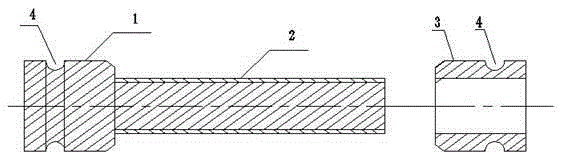
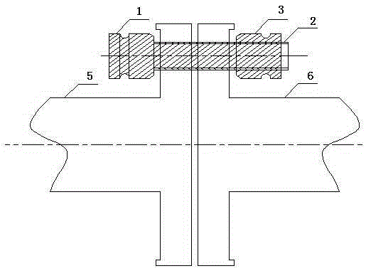
[0014] like figure 1 , 2 As shown, the present invention is a rotor coupling center alignment disk device of a turbogenerator, including a connecting shaft pin 1 . According to the different sizes of the rotors of the unit, measure the inner hole of the active rotor coupling and the thickness of the coupling respectively, and process and manufacture a suitable connecting shaft pin 1 . One end of the connecting pin is provided with a limit boss, and the other end of the connecting pin is covered with a movable wire rope bolt hanger 3, and a circle of rope grooves 4 is arranged on the circumference of the limit boss and the wire rope bolt hanger 3. The surface of the connecting shaft pin 1 is provided with a protective copper sleeve 2, which can prevent the connecting shaft pin 1 from causing mechanical damage to the inner hole of the precise rotor coupling.

[0015]...


PUM


Abstract

The invention discloses a center aligning disk driving device for a rotor coupling of a steam turbine generator unit. The center aligning disk driving device comprises a connecting shaft pin, wherein the connecting shaft pin passes through a driving rotor coupling inner hole and a driven rotor coupling inner hole which are formed oppositely side by side in sequence; a limiting boss positioned on the outer side of the driving rotor coupling inner hole is arranged at one end of the connecting pin shaft; the other end of the connecting shaft pin is movably sleeved with a steel wire rope hanging sleeve positioned on the outer side of the driven rotor coupling inner hole; the circumference of the limiting boss and the circumference of the steel wire rope hanging sleeve are provided with a circle of rope winding groove respectively; a protection copper sleeve is arranged on the surface of the connecting shaft pin. The center aligning disk driving device has the beneficial effects that a driven rotor stress point is added, and a driving rotor and a driven rotor can rotate consistently during disk driving of the rotors, so that two adjacent rotors are subjected to synchronous disk driving simultaneously, the influence of external force is overcome, and the positions of the rotors can be kept consistent after appropriate measurement.

Description

technical field [0001] The invention relates to a center alignment disk device of a rotor coupling of a turbogenerator set. Background technique [0002] With the development of science and technology and equipment manufacturing industry, the single unit capacity of modern large-scale turbo-generator sets continues to increase. The operating parameters and equipment structure are also constantly changing, and the number of cylinders and rotors also develops from the initial single cylinder and single rotor to multi-cylinder and multi-rotor. In the installation and overhaul project of electric power construction, the alignment accuracy of the rotor coupling center of the turbo-generator unit has always been one of the important factors determining the quality of the entire project. It directly determines whether the turbo-generator unit can operate safely and stably. At this stage, the technical specifications of electric power construction and the manufacturing plant genera...

Claims


Application Information

Patent Timeline
Patent Type & Authority Patents(China)
IPC IPC(8): F16D1/033
Inventor 邵德让赵立波梁强刘进卓
Owner POWERCHINA SEPCO1 ELECTRIC POWER CONSTR CO LTD
Why Eureka
Try Eureka