Tri-mount cradle system

a cradle system and tri-mount technology, applied in the field of systems, can solve the problems of large size and weight of military operations, large amount of material, and high cost, and achieve the effects of enhancing thickness, strengthening strength, and enhancing thickness

Active Publication Date: 2011-06-21
KIESLER POLICE SUPPLY
View PDF13 Cites 10 Cited by
  • Summary
  • Abstract
  • Description
  • Claims
  • Application Information

AI Technical Summary

Benefits of technology

[0012]In one embodiment of the invention, the cradle and its concomitant front and rear inserts are machined from a single piece of aluminum having one side comprising material having a significantly enhanced thickness. This embodiment of the invention provides for a plurality of weapon contact points that remain consistent in their positions relative to the weapon components over time and under rugged conditions as encountered in the field, as well as an enhanced strength portion of the cradle capable of supporting the weight of an ammunition can mounted thereto.
[0013]The cradle of the present invention further comprises a pair of spaced pintle flanges each having a retaining pin aperture therein for accepting a retaining pin. A pintle having a pin aperture therethrough is positioned between the spaced pint

Problems solved by technology

Weapons suited for use in military operations often have a size and weight that prohibits them from being employed by a user because they cannot be accurately aimed or stabilized without being mounted to a platform of some type, for example the bed of a truck or jeep.
However, most of these prior art systems are fairly complex, both in operation and in their manufacture, and as a result they are prone to failure under demanding operating conditions.
However, in many of these systems the mating po

Method used


Image

  • Tri-mount cradle system
  • Tri-mount cradle system
  • Tri-mount cradle system

Examples


Embodiment Construction

)

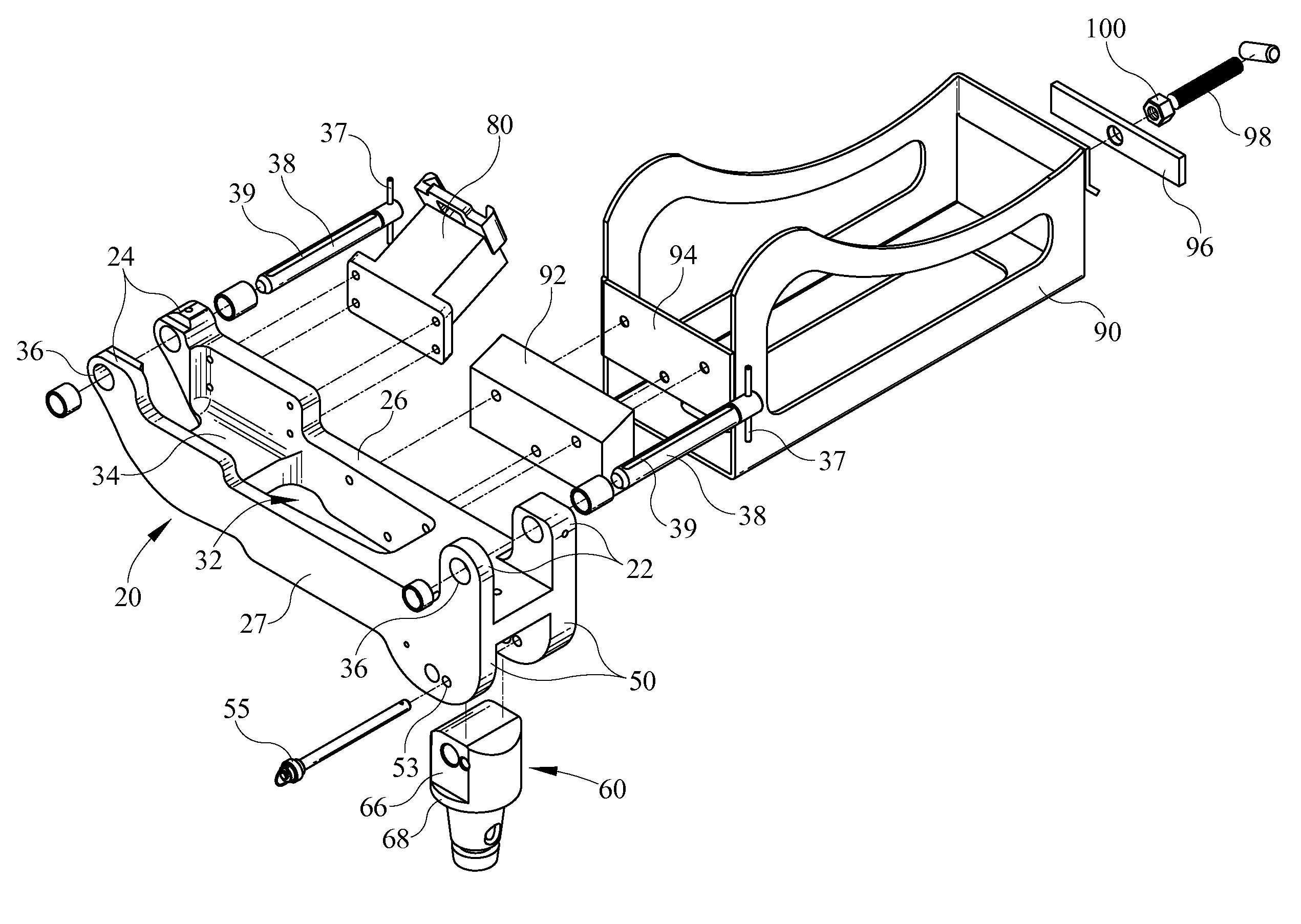
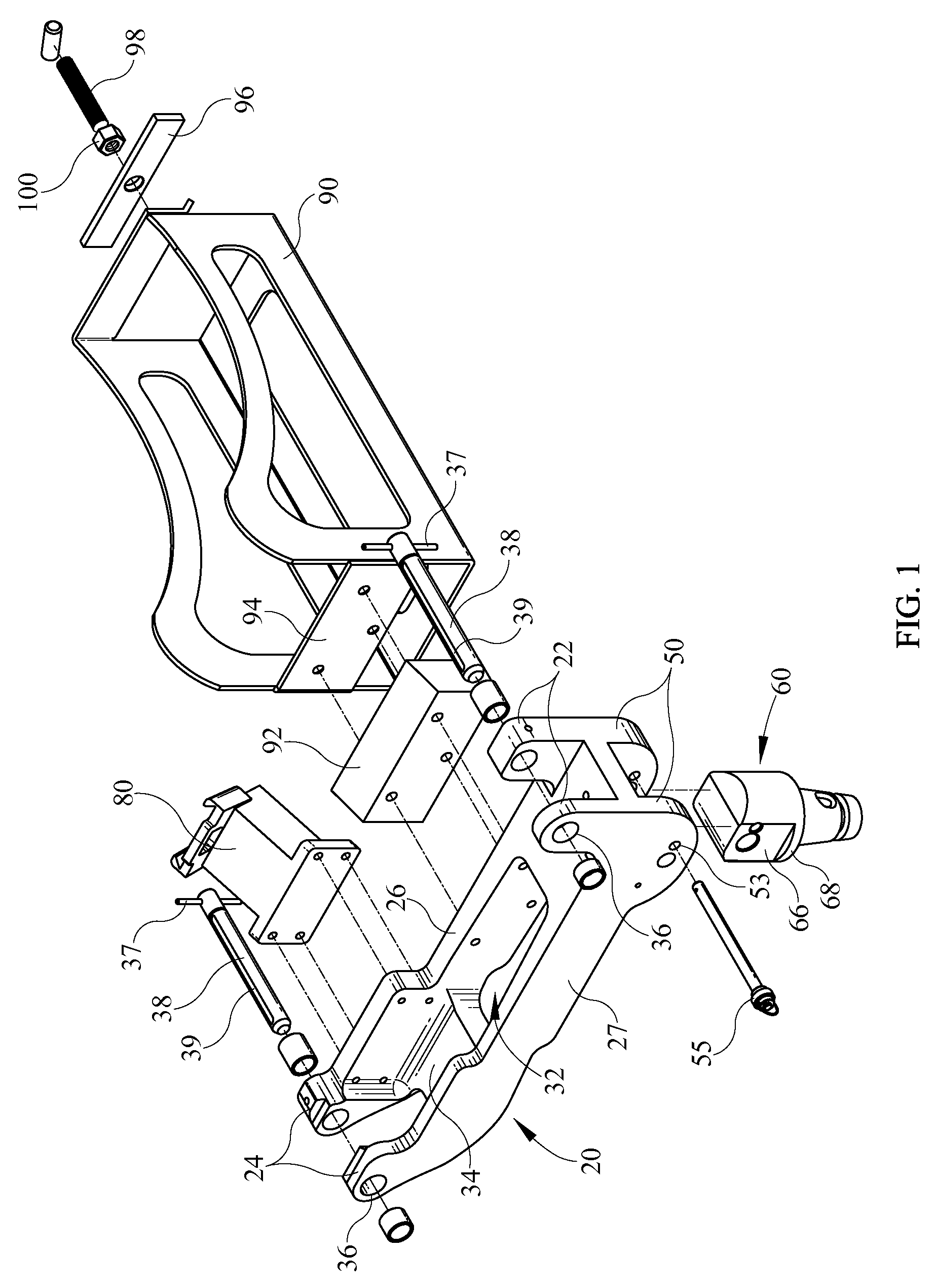
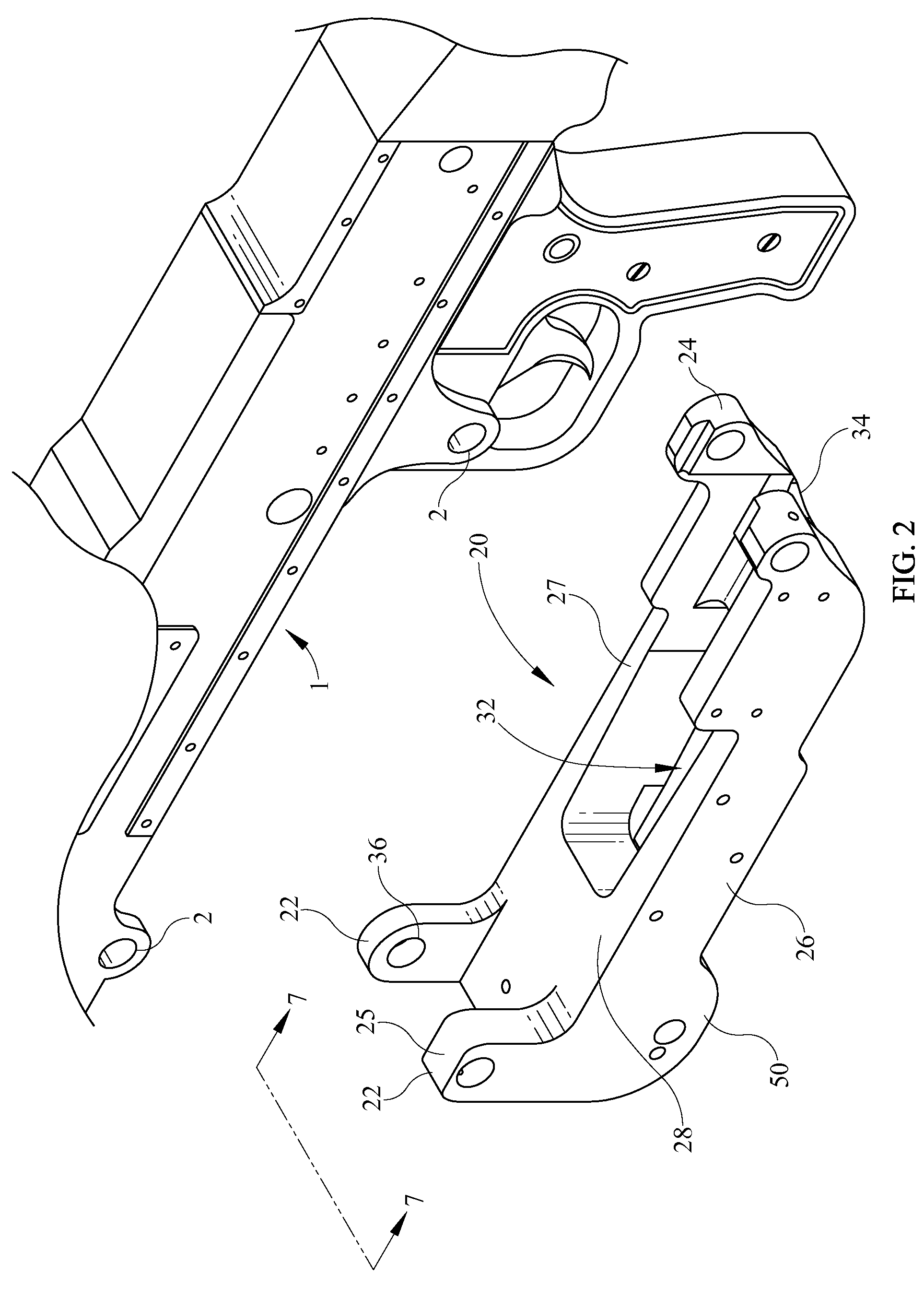
[0025]Referring now to FIGS. 1 and 2, and in accordance with a preferred constructed embodiment of the present invention, a weapon mounting system 10 for securing a weapon 1 such as a machine gun to a platform includes a cradle 20 having a front and rear opposed flanges 22 and 24 respectively for supporting weapon 1 in a usable position. While the present system 10 may be adapted for use with a wide variety of weapons 1 the exemplary embodiments included herein refer primarily to a machine gun type weapon including but not limited to an M249 light machine gun, M240 medium machine gun, and MAG58 machine gun that are engaged by cradle 20 when weapon 1 is properly secured thereto.

[0026]Cradle 20 may comprise a pair of opposed first and second side portions, 26 and 27 respectively, that terminate at a rear end in rear flange 24 and terminate at a front end in front flange 22. Side portions 26, 27 are arranged generally in the same vertical plane as front 22 and rear 24 flanges, thus pr...


PUM


Abstract

A weapon mounting system for securing a weapon such as a machine gun to a platform comprises a cradle assembly including a pair of opposed front and rear flanges having apertures therein for engaging a retaining pin to secure a weapon thereto. The cradle assembly of the present invention is formed of a single piece of high strength material, for example aluminum stainless steel or titanium. The cradle assembly further includes a pair of pintle flanges to engage a pintle, thereby enabling rotation of cradle and concomitant weapon around two axes.

Description

BACKGROUND OF THE INVENTION[0001]1. Field of the Invention[0002]The present invention relates generally to a system for securing a weapon to a platform and more particularly to a weapon cradle system having a cradle that is readily secured to a plurality of machine gun or rifles having a pair of spaced attachment points. The invention further comprises a reinforced cradle that is capable of being rotated around two axes when secured to a pintle and concomitant weapon mount.[0003]2. Description of the Related Art[0004]Weapons suited for use in military operations often have a size and weight that prohibits them from being employed by a user because they cannot be accurately aimed or stabilized without being mounted to a platform of some type, for example the bed of a truck or jeep. In order to obviate this difficulty, mounting devices of various designs have been employed in an attempt provide a mechanism for reliably securing the weapon to a platform, while simultaneously making it ...

Claims


Application Information

Patent Timeline
IPC IPC(8): F41A23/04
CPCF41A27/14
Inventor BROOKS, ADAM S.
Owner KIESLER POLICE SUPPLY
Why Eureka
Try Eureka