Tobacco leaf shredding equipment for tobacco processing
A tobacco leaf and shredded technology, which is applied in the field of tobacco leaf shredded equipment for tobacco processing, can solve the problems of troublesome operation, hand cuts, and labor, and achieve the effect of convenient operation and convenient collection
- Summary
- Abstract
- Description
- Claims
- Application Information
AI Technical Summary
Problems solved by technology
Method used
Image
Examples
Embodiment 1
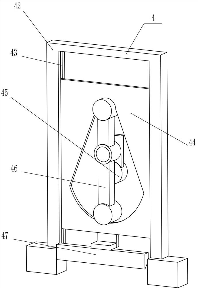
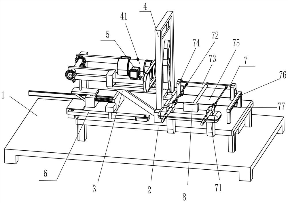
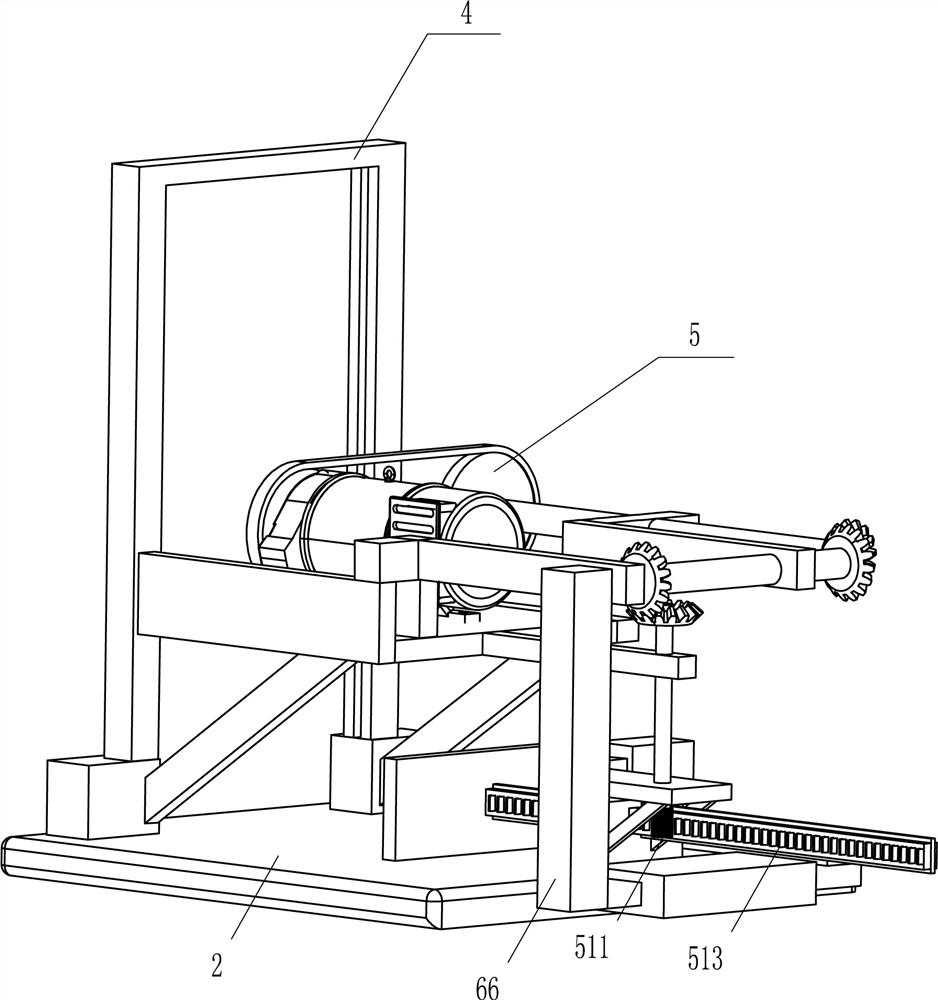
[0025] A tobacco cutting equipment for tobacco processing, such as Figure 1-Figure 5 As shown, it includes a base 1, a rectangular frame 2, a bracket 3, a wire cutting mechanism 4, a transmission mechanism 5, and a sliding mechanism 6. The top of the base 1 is fixedly connected with a rectangular frame 2, and the middle of the top of the rectangular frame 2 is fixedly connected with a bracket 3. 3 is provided with a shredded mechanism 4, and the left side of the top of the rectangular frame 2 is provided with a transmission mechanism 5, and the transmission mechanism 5 is connected with the shredded mechanism 4, and the left side of the rectangular frame 2 is provided with a sliding mechanism 6, and the sliding mechanism 6 is connected with the transmission mechanism 5. connect.
[0026] The wire cutting mechanism 4 includes a motor 41, a first fixed plate 42, a slotted slide plate 44, an eccentric shaft 45, a swing lever 46 and a cutting knife 47, a motor 41 is arranged in t...
Embodiment 2
[0034] On the basis of Example 1, such as figure 1 Shown, also include pusher mechanism 7, pusher mechanism 7 includes fixed frame 71, cylinder 72, the 3rd fixed plate 73, limit special-shaped block 74, pusher plate 75, slide block 76 and slide guide plate 77, The right side of the front side of the rectangular frame 2 is fixedly connected with a fixed mount 71, and the top of the fixed mount 71 is symmetrically provided with a cylinder 72. The left and right sides are all fixedly connected with the limited special-shaped block 74, and the right side of the top of the rectangular frame 2 is fixedly connected with a sliding guide plate 77, and the sliding type in the sliding guide plate 77 is provided with a slide block 76, and the rotary type on the left side of the slide block 76 is connected with a pusher. The material plate 75 and the material pushing plate 75 are located in the limit special-shaped blocks 74 on the left and right sides and are in contact with them.
[003...
Embodiment 3
[0037] On the basis of embodiment 1 and embodiment 2, such as Figure 1-Figure 2 As shown, a guide rod 8 is also included. The guide rod 8 is fixedly connected to the middle of the top of the fixing frame 71 , and the rear end of the guide rod 8 passes through the middle part of the third fixing plate 73 to slide and fit with it.
[0038] It also includes a collection frame 9 fixedly connected to the rear part of the top right side of the base 1 .
[0039] When the telescopic rod of the cylinder 72 drives the third fixed plate 73 to move, the guide rod 8 plays a guiding role on the third fixed plate 73, so that the third fixed plate 73 can be moved more firmly.
[0040] When the pushing plate 75 moves backward and the shredded tobacco is released, the shredded tobacco then falls into the collection frame 9, and when an appropriate amount of shredded tobacco is accumulated in the collection frame 9, the shredded tobacco in the collection frame 9 is taken out for processing. In...
PUM
 Abstract
Description
Claims
Application Information
 - R&D
- Intellectual Property
- Life Sciences
- Materials
- Tech Scout
- Unparalleled Data Quality
- Higher Quality Content
- 60% Fewer Hallucinations
Browse by: Latest US Patents, China's latest patents, Technical Efficacy Thesaurus, Application Domain, Technology Topic, Popular Technical Reports.
© 2025 PatSnap. All rights reserved.Legal|Privacy policy|Modern Slavery Act Transparency Statement|Sitemap|About US| Contact US: help@patsnap.com


