
Spraying tool and spraying production line

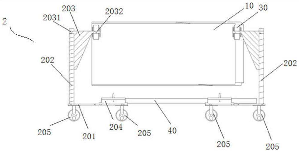
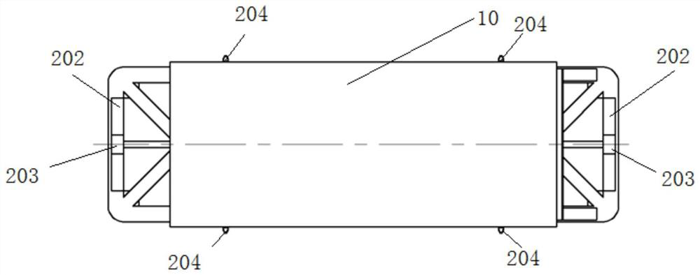
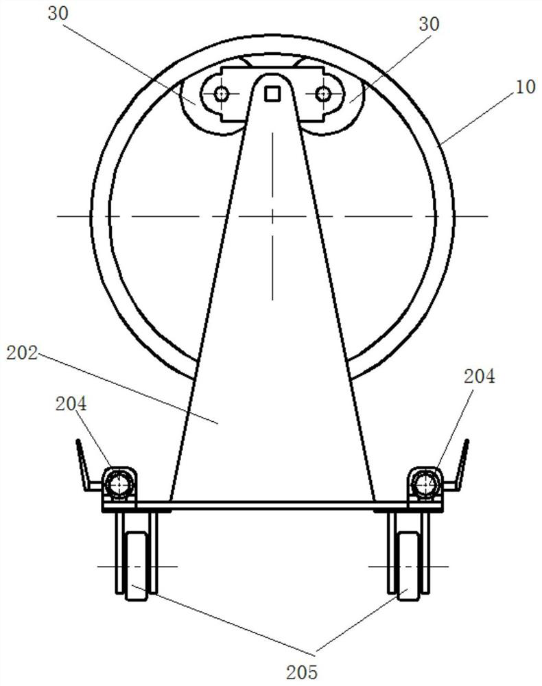
A technology of tooling and spraying machine, applied in spraying device, spraying room, etc., can solve the problems of not being able to spray at one time, occupying work platform, wasting time, etc., to avoid uneven spraying, improve production efficiency, and achieve good spraying effect.

Pending Publication Date: 2021-01-08
SHANXI FENXI HEAVY IND
View PDF0 Cites 0 Cited by
  • Summary
  • Abstract
  • Description
  • Claims
  • Application Information

AI Technical Summary

Problems solved by technology

[0002] There are usually two methods for spraying the cylindrical rotary shell. First, place the shell vertically on the workbench and spray around it. The disadvantages of this method are: a. Vertical placement is easy to dump and can be damaged If the quality accident is caused, the operator needs to provide additional protection; b. After the outer surface is sprayed, it cannot be transported with a sling, and the work platform is occupied to cause waiting; second, the shell is placed flat on the rotary cart for spraying, and the rotary cart uses two pairs of The rubber runner supports the rotary shell, and the operator can rotate the upper part 180° to spray the other side after spraying. The disadvantages of this method: a. After half of the spraying is completed, it needs to wait for drying before spraying the other side, resulting in a waste of time ; b. Long intervals between two sprays or inconsistent paint ratios will cause color difference; c. The thickness of the joint between two sprays should be greater than the average thickness
[0003] Both of the above two methods have the problem of uneven spraying and cannot be sprayed at one time

Method used


Image

  • Spraying tool and spraying production line
  • Spraying tool and spraying production line
  • Spraying tool and spraying production line

Examples


Embodiment Construction

[0022] The following will clearly and completely describe the technical solutions in the embodiments of the present invention with reference to the accompanying drawings in the embodiments of the present invention. Obviously, the described embodiments are only some of the embodiments of the present invention, not all of them. Based on the embodiments of the present invention, all other embodiments obtained by persons of ordinary skill in the art without making creative efforts belong to the protection scope of the present invention.

[0023] It should be noted that when an element is referred to as being “fixed” or “disposed on” another element, it may be directly on the other element or be indirectly on the other element. When an element is referred to as being "connected to" another element, it can be directly connected to the other element or indirectly connected to the other element.

[0024] It is to be understood that the terms "length", "width", "top", "bottom", "front"...


PUM


Abstract

The invention discloses a spraying tool and a spraying production line which are used for spraying a revolving body workpiece with openings in the two ends. The spraying tool comprises a spraying machine used for spraying paint to the revolving body workpiece, and further comprises two fixing parts, rollers and an adjustable rod, wherein the two fixing parts are oppositely arranged and used for supporting the revolving body workpiece; the rollers are fixedly arranged on the two fixing parts and used for driving the revolving body workpiece to rotate; and the adjustable rod is used for adjusting the distance between the two fixing parts. The spraying tool can achieve one-time spraying forming and has the advantages of being high in production efficiency and the like. The spraying productionline adopts the spraying tool.

Description

technical field [0001] The invention relates to the technical field of spraying, in particular to a spraying tool and a spraying production line. Background technique [0002] There are usually two methods for spraying the cylindrical rotary shell. First, place the shell vertically on the workbench and spray around it. The disadvantages of this method are: a. Vertical placement is easy to dump and can be damaged If the quality accident is caused, the operator needs to provide additional protection; b. After the outer surface is sprayed, it cannot be transported with a sling, and the work platform is occupied to cause waiting; second, the shell is placed flat on the rotary cart for spraying, and the rotary cart uses two pairs of The rubber runner supports the rotary shell, and the operator can rotate the upper part 180° to spray the other side after spraying. The disadvantages of this method: a. After half of the spraying is completed, it needs to wait for drying before spray...

Claims


Application Information

Patent Timeline
Patent Type & Authority Applications(China)
IPC IPC(8): B05B13/02B05B16/00
CPCB05B13/0228B05B16/00
Inventor 郭凯陈磊吴群郑胜刘娟杨忠丰关飞张鹏候素明梁福顺刘彧
Owner SHANXI FENXI HEAVY IND
Learn More