Foundation stone screening equipment for road

A screening equipment and cornerstone technology, applied in the fields of sieving, recycling technology, solid separation, etc., can solve the problems of low labor intensity, low efficiency of cornerstone screening, and high labor intensity, so as to reduce labor intensity and improve screening efficiency. Effect

Active Publication Date: 2021-01-08
SHANXI YUANFANG ROAD & BRIDGE GROUP +1
View PDF9 Cites 9 Cited by
  • Summary
  • Abstract
  • Description
  • Claims
  • Application Information

AI Technical Summary

Problems solved by technology

[0005] The present invention overcomes that when people screen cornerstones for roads, it is necessary to move the sieve back and forth through the cooperation of two people to complete the screening of cornerstones. In this way, the labor intensity of manual operation is relatively high, and the efficiency of screening cornerstones is low. However, the technical problem to be solved by the present invention is to provide a road cornerstone screening equipment with relatively low labor intensity of manual operation and relatively high efficiency in cornerstone screening.

Method used


Image

  • Foundation stone screening equipment for road
  • Foundation stone screening equipment for road
  • Foundation stone screening equipment for road

Examples


Embodiment 1

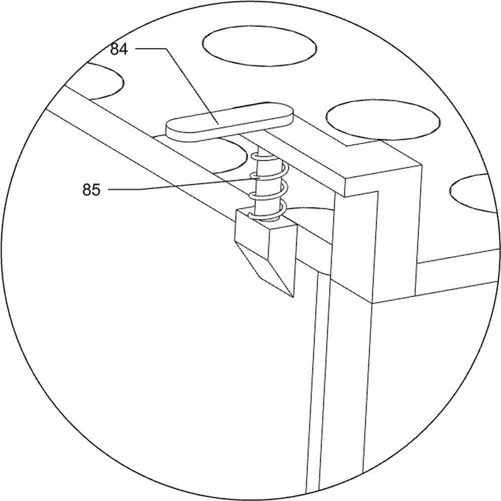
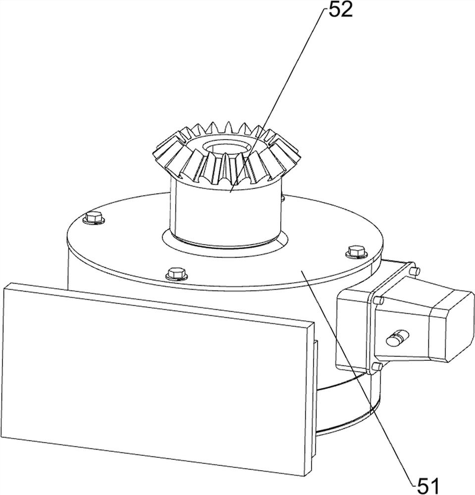
[0029] A kind of foundation stone screening equipment for highway, such as Figure 1 to Figure 3 and Figure 5 to Figure 9 As shown, it includes a bottom plate 1, a mounting frame 2, a material receiving box 3, a material discharging box 4, a driving mechanism 5, a swing mechanism 6, a switch plate mechanism 8, a pushing mechanism 9, a clamping mechanism 10 and a blanking mechanism 11, and the bottom plate The right side of the top of 1 is connected with a driving mechanism 5, the front and rear sides of the top of the base plate 1 are connected with mounting frames 2, and the upper parts of the two mounting frames 2 are connected with a swing mechanism 6, and the middle part of the swing mechanism 6 is slidingly connected with a The material receiving box 3, and the front and rear sides of the material receiving box 3 are all provided with card slots, the bottom of the material receiving box 3 right side is provided with a through hole, and a locking mechanism 10 is connected...

Embodiment 2

[0038] On the basis of Example 1, such as Figure 4 Shown, also comprise ejection mechanism 7, ejection mechanism 7 comprises positioning plate 71, cylinder 72 and support rod 73, the right side of discharging box 4 is connected with two support rods 73, between two support rods 73 Connect with cylinder 72, and the telescoping link of cylinder 72 is connected with the right side of slide plate, and positioning plate 71 is connected between cylinder 72 and the upper part of discharging box 4 right sides.

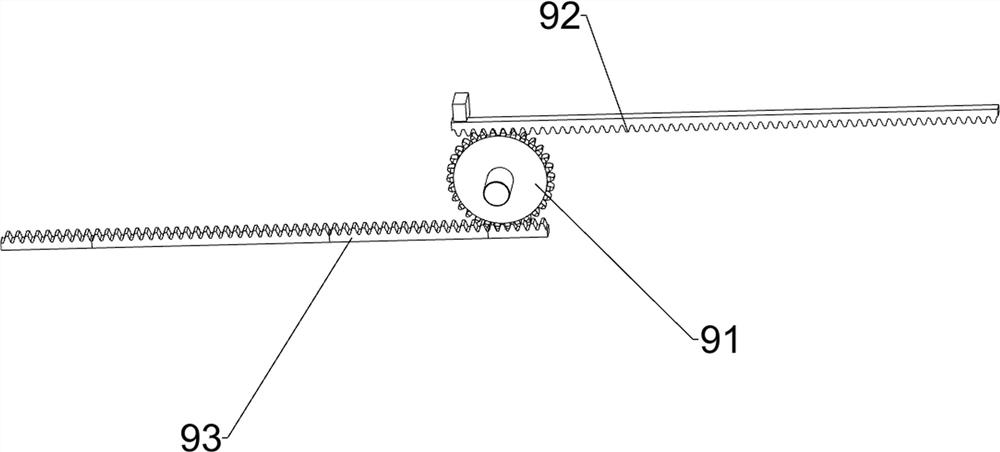
[0039] When the cornerstone in the discharge box 4 has been screened, people need to push the slide plate to slide to the left, start the cylinder 72 to extend its telescopic rod, and the slide plate drives the first rack frame 92 to slide to the left, and the transmission gear 91 drives the second rack frame 93 and the material receiving box 3 to slide to the right thereupon, after the cornerstone in the material discharging box 4 and the material receiving box 3 has been cl...


PUM


Abstract

The invention relates to foundation stone screening equipment, in particular to foundation stone screening equipment for a road. The foundation stone screening equipment for the road is relatively lowin labor intensity of manual operation and relatively high in foundation stone screening efficiency. In order to solve the technical problem, the foundation stone screening equipment for the road comprises a driving mechanism, mounting frames, a swinging mechanism and a material receiving box, wherein the driving mechanism is connected to a bottom plate; the at least two mounting frames are arranged and connected to the side, close to the driving mechanism, of the bottom plate; the swinging mechanism is connected between the two mounting frames; and the material receiving box is connected tothe swing mechanism in a sliding manner, and a clamping groove is formed in the material receiving box. Under the action of the driving mechanism, the swinging mechanism, a switch plate mechanism, a pushing mechanism, a clamping mechanism and a discharging mechanism, foundation stones for the road can be quickly and uniformly screened.

Description

technical field [0001] The invention relates to a cornerstone screening device, in particular to a cornerstone screening device for roads. Background technique [0002] The literal meaning of highway is public road, public transportation road, many vehicles such as automobiles, bicycles, rickshaws, horses and pedestrians can walk. There were no restrictions on the early roads, mostly simple roads. Later, different roads had different restrictions; due to the increasingly developed traffic, more and more roads were restricted to use, and this type of expressway was developed, which is exclusively for the closed use of cars. When people pave the road, they need to lay a layer of cornerstone on the road to make the construction of the road more firm, thereby prolonging the service life of the road, achieving the purpose of cost saving and driving safety. [0003] At present, when people screen cornerstones for highways, they need to cooperate with two people to move the sieve ...

Claims


Application Information

Patent Timeline
Patent Type & Authority Applications(China)
IPC IPC(8): B07B1/28B07B1/42B07B1/46B07B1/52
CPCB07B1/28B07B1/42B07B1/46B07B1/526Y02W30/62
Inventor 汤双琴
Owner SHANXI YUANFANG ROAD & BRIDGE GROUP
Why Eureka
Try Eureka