Supercharge Your Innovation With Domain-Expert AI Agents!

Numerical control gantry milling machine spindle convenient to disassemble

A technology of gantry milling machine and spindle, which is applied in the direction of milling machine equipment, milling machine equipment details, large fixed members, etc. It can solve the problems of inconvenient disassembly and achieve the effect of easy disassembly and avoiding breakage

Inactive Publication Date: 2021-01-08
黄石百斯特智能科技有限公司
View PDF0 Cites 2 Cited by
  • Summary
  • Abstract
  • Description
  • Claims
  • Application Information

AI Technical Summary

Problems solved by technology

[0003] The purpose of the present invention is to solve the disadvantage of being inconvenient to disassemble in the prior art, and propose a CNC gantry milling machine spindle that is easy to disassemble

Method used


Image

  • Numerical control gantry milling machine spindle convenient to disassemble
  • Numerical control gantry milling machine spindle convenient to disassemble

Examples


Embodiment Construction

[0012] The following will clearly and completely describe the technical solutions in the embodiments of the present invention with reference to the accompanying drawings in the embodiments of the present invention. Obviously, the described embodiments are only some, not all, embodiments of the present invention.

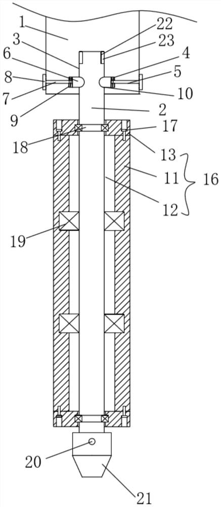
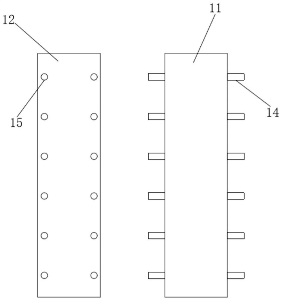
[0013] refer to Figure 1-2 , a CNC gantry milling machine spindle that is easy to disassemble, including a drive shaft 1, a spindle 2, a spindle housing 16, and a fixed chuck 21, and a fixed groove 3 matching the shape of the spindle 2 is opened at the axis center of the end surface of the drive shaft 1, The inner wall of the fixed groove 3 is provided with a number of limiting grooves 4 along the circumference, and the surface of the drive shaft 1 is provided with a connecting groove 5 communicating with the limiting groove 4. A limiting block 6 is installed in the limiting groove 4, and the limiting block 6 is close to the side of the main shaft 2. The shape is se...


PUM


Abstract

The invention relates to the technical field of numerical control gantry milling machine spindles, in particular to a numerical control gantry milling machine spindle convenient to disassemble. The numerical control gantry milling machine spindle comprises a driving shaft, a spindle body, a spindle box and a fixing chuck; a fixing groove matched with the spindle body in shape is formed in the axisof the surface of the tail end of the driving shaft, a plurality of limiting grooves are formed in the inner wall of the fixing groove in the circumferential direction, connecting grooves communicating with the limiting grooves are formed in the surface of the driving shaft, limiting blocks are installed in the limiting grooves, connecting rods are fixedly connected to the tail ends of one sidesof the limiting blocks through the connecting grooves, push plates are fixedly connected to the tail ends of the connecting rods, and the connecting rods between the bottom ends of the limiting blocksand the limiting grooves are provided with reset springs in a sleeved mode; and arc-shaped grooves matched with the limiting blocks in shape are formed in the surface of the upper part of the spindlebody in the circumferential direction, the upper part of the spindle body is inserted into the fixing groove, the spindle box is arranged on the outer side of the lower part of the spindle body, andthe fixing chuck is fixedly installed at the tail end of the spindle body through second fixing bolts. The numerical control gantry milling machine spindle has the advantage of being convenient to disassemble.

Description

technical field [0001] The invention relates to the technical field of a CNC gantry milling machine spindle, in particular to a CNC gantry milling machine spindle that is easy to disassemble. Background technique [0002] Gantry milling machine, referred to as gantry milling machine, is a milling machine with a portal frame and a horizontal long bed. The gantry milling machine can use multiple milling cutters to process the surface at the same time, the machining accuracy and production efficiency are relatively high, and it is suitable for processing the plane and inclined plane of large workpieces in batch and mass production. CNC gantry milling machines can also process space surfaces and some special parts. It takes a lot of time to disassemble the main shaft of the existing CNC gantry milling machine, which is inconvenient for maintenance and replacement. Now there is a need for a CNC gantry milling machine main shaft that is easy to disassemble. Contents of the inve...

Claims


Application Information

Patent Timeline
IPC IPC(8): B23C9/00B23B19/02
CPCB23C9/00B23Q1/70
Inventor 方辉
Owner 黄石百斯特智能科技有限公司
Features
  • R&D
  • Intellectual Property
  • Life Sciences
  • Materials
  • Tech Scout
  • Unparalleled Data Quality
  • Higher Quality Content
  • 60% Fewer Hallucinations
Learn More