Polishing equipment for stainless steel dinner plate machining

A stainless steel, dinner plate technology, applied in metal processing equipment, grinding/polishing equipment, machine tools with surface polishing, etc., can solve the problems of slow polishing speed, low work efficiency, more time and energy, etc. High polishing speed and anti-movement effect

Active Publication Date: 2021-01-08
揭阳市庆展不锈钢有限公司
View PDF16 Cites 4 Cited by
  • Summary
  • Abstract
  • Description
  • Claims
  • Application Information

AI Technical Summary

Problems solved by technology

[0005] In order to overcome the disadvantages of manually polishing the interior of the stainless steel dinner plate, it takes more time and effort, the work efficiency is low, and the polishing speed is slow, the technical problem to be solved by the invention is to provide a time-saving, labor-saving, and work-efficient Polishing equipment for processing stainless steel dinner plates with high precision and fast polishing speed

Method used


Image

  • Polishing equipment for stainless steel dinner plate machining
  • Polishing equipment for stainless steel dinner plate machining
  • Polishing equipment for stainless steel dinner plate machining

Examples


Embodiment 1

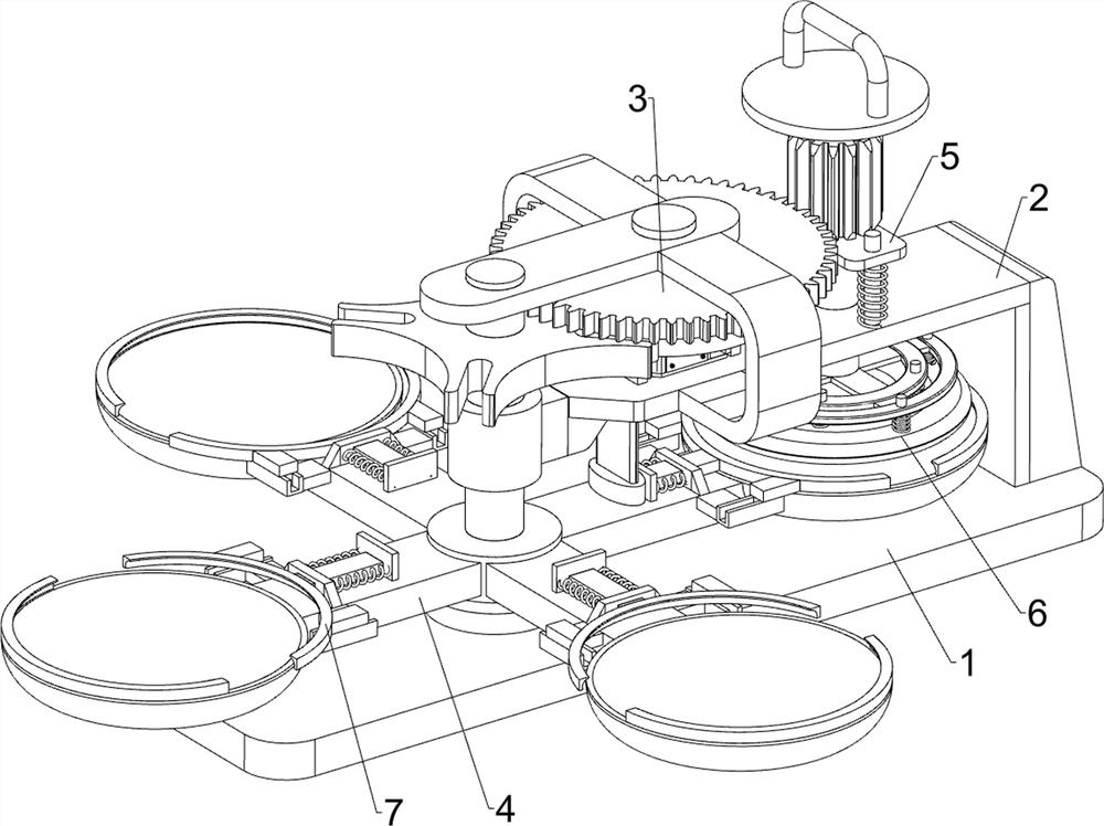
[0024] A kind of polishing equipment for stainless steel dinner plate processing, such as Figure 1 to Figure 4 As shown, it includes a bottom plate 1, a mounting frame 2, a power mechanism 3, a rotating frame mechanism 4, a movable frame mechanism 5, and a polishing mechanism 6. The top right side of the bottom plate 1 is connected with a mounting frame 2, and a power mechanism is respectively installed on the mounting frame 2. 3 and the movable frame mechanism 5, the movable frame mechanism 5 is connected with the power mechanism 3 by transmission, the bottom plate 1 top left side is equipped with a rotary frame mechanism 4, the rotary frame mechanism 4 is connected with the power mechanism 3 by transmission, and the movable frame mechanism 5 is equipped with a polishing mechanism 6.

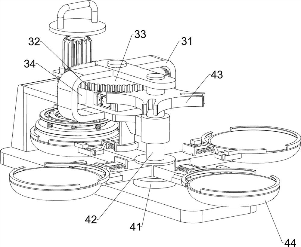
[0025] The power mechanism 3 includes a fixed frame 31, a servo motor 32, a first gear 33 and a push rod 34, the left part of the mounting frame 2 is connected with the fixed frame 31, the top...

Embodiment 2

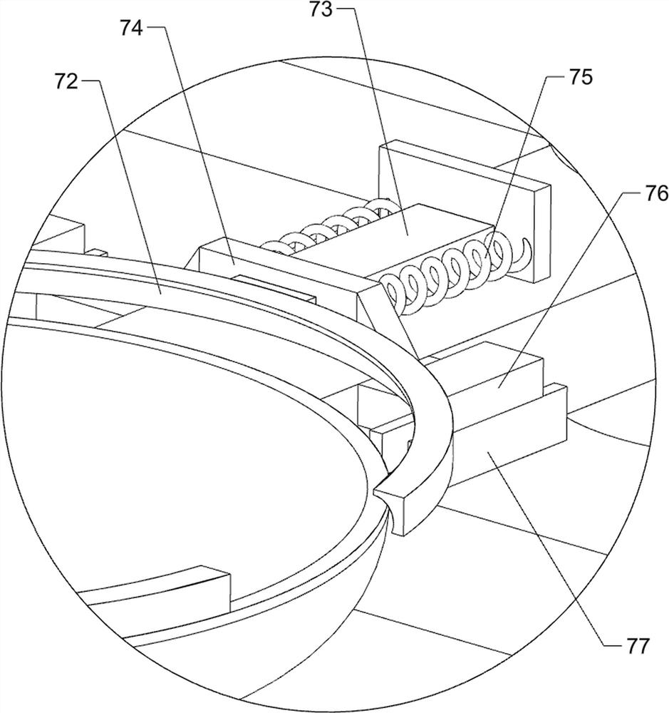
[0031] On the basis of Example 1, such as image 3 with Figure 5As shown, a clamping mechanism 7 is also included, and the clamping mechanism 7 includes a fixed arc collar 71, a movable arc collar 72, a sliding push block 73, a guide block 74, a return spring 75, a guide slider 76, a guide rail 77 and top block 78, bracket 44 top outsides are connected with fixed arc collar 71, bracket 44 top insides are connected with guide block 74, are connected with sliding push block 73 in the guide block 74, are connected on the slide push block 73 There are movable arc-shaped collars 72, two return springs 75 are connected between the sliding push block 73 and the guide block 74, two guide sliders 76 are connected to the outer wall of the movable arc-shaped collar 72, and the lower part of the guide slider 76 is slidingly connected Guide rail 77 is arranged, and guide rail 77 is connected with the outer surface of bracket 44, and top left side is connected with top block 78 in mountin...


PUM


Abstract

The invention relates to internal polishing equipment for machining, in particular to polishing equipment for stainless steel dinner plate machining. The polishing equipment for stainless steel dinnerplate machining is time-saving, labor-saving, high in working efficiency and high in polishing speed. The polishing equipment for stainless steel dinner plate machining provided by the invention comprises a bottom plate, a power mechanism, a rotary rack mechanism and a movable rack mechanism, wherein a mounting frame is connected to one side of the bottom plate; the power mechanism is mounted onthe mounting frame; the rotary rack mechanism is installed on the other side of the bottom plate; the rotary rack mechanism is in transmission connection with the power mechanism; and the movable rackmechanism is mounted on the mounting frame. According to the polishing equipment, power can be provided for the rotary rack mechanism and the movable rack mechanism through the power mechanism; stainless steel dinner plates can be conveyed to the polishing mechanism through the rotary rack mechanism; the polishing mechanism can be driven to work through the movable rack mechanism; and the polishing mechanism works to polish the interior of the stainless steel dinner plates in an omnibearing mode.

Description

technical field [0001] The invention relates to an internal polishing device for processing, in particular to a polishing device for processing stainless steel dinner plates. Background technique [0002] In order to make the inside of the stainless steel dinner plate smooth and beautiful, it is necessary to polish the inside of the stainless steel dinner plate, remove the burrs inside the stainless steel dinner plate, and then proceed to the next step of processing. At present, polishing the inside of the stainless steel dinner plate is generally done manually When manually polishing the interior of the stainless steel dinner plate, with the help of a polishing sheet, one hand fixes the stainless steel dinner plate, and the other hand holds the polishing sheet, and makes the polishing sheet continuously rotate along the inner wall of the stainless steel dinner plate. More time and energy, and the workload of the workers is larger, the work efficiency is low, and the polishi...

Claims


Application Information

Patent Timeline
Patent Type & Authority Applications(China)
IPC IPC(8): B24B29/02B24B41/04B24B41/06B24B47/12B24B47/20
CPCB24B29/02B24B41/06B24B41/04B24B47/12B24B47/20Y02P70/10
Inventor 罗紫武
Owner 揭阳市庆展不锈钢有限公司
Why Eureka
Try Eureka