Multifunctional textile placing box

A technology for textiles and placing boxes, which is applied in the field of placing boxes, and can solve problems such as easy damage

Active Publication Date: 2021-01-08
NANJING HANXIYUE AUTOMATION TECH CO LTD
View PDF8 Cites 2 Cited by
  • Summary
  • Abstract
  • Description
  • Claims
  • Application Information

AI Technical Summary

Problems solved by technology

[0005] In order to overcome the shortcomings in the prior art that textiles are easily damaged when placed in the air for a long time, and the textiles need to be fixed, the technical problem of the present invention is to provide a textile that can be fixedly placed in a transparent box, and can be fixed by hand. Versatile textile storage bins that touch the textiles directly

Method used


Image

  • Multifunctional textile placing box
  • Multifunctional textile placing box
  • Multifunctional textile placing box

Examples


Embodiment 1

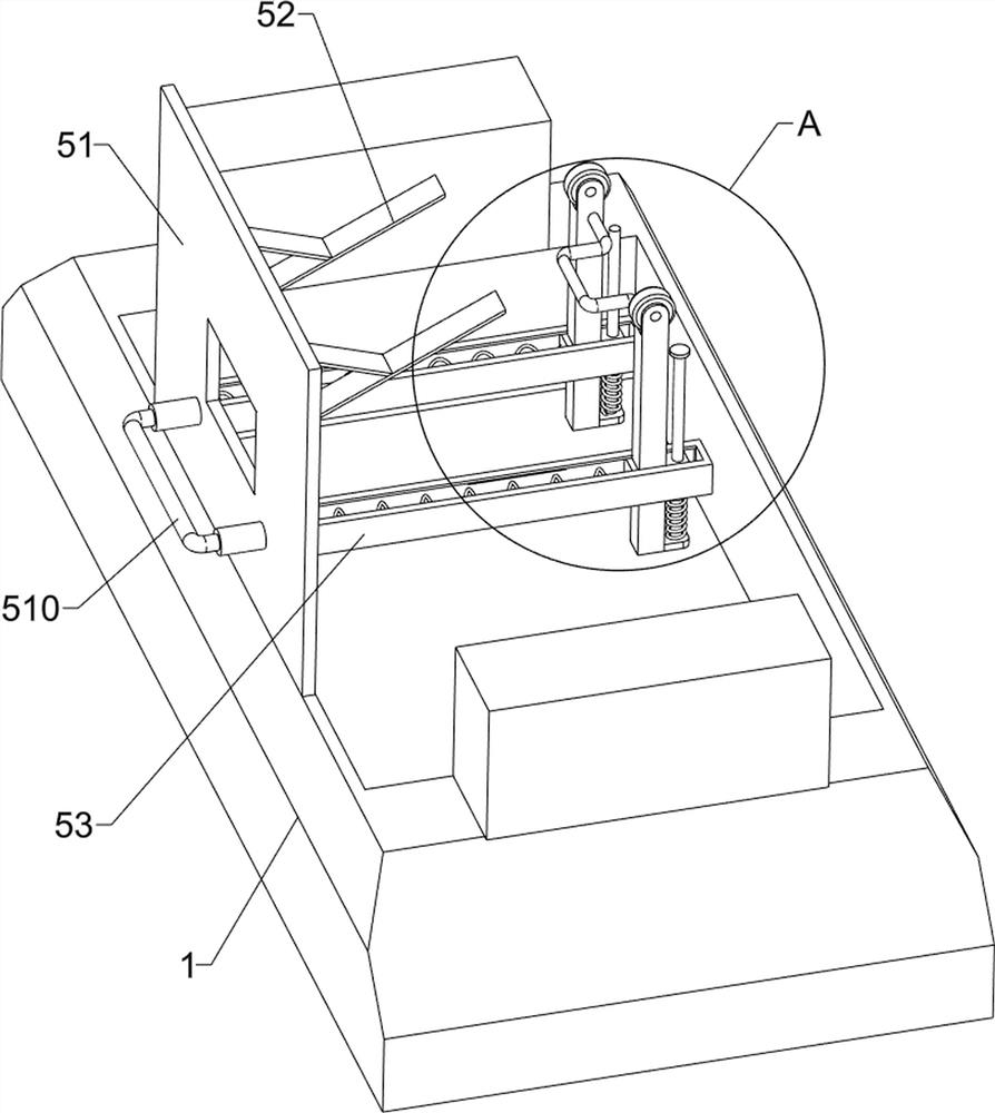
[0024] A multifunctional textile storage box, such as figure 1 , figure 2 , image 3 , Figure 4 and Figure 5 As shown, it includes a support 1, a glass cabinet 2, a cover plate 3, a clamping assembly 4 and a retrieving assembly 5. A glass cabinet 2 is installed on the top of the support 1, and the top of the glass cabinet 2 is rotatably provided with a cover plate 3, and the glass The left and right sides of the cabinet 2 are provided with a clamping assembly 4, and the lower part of the glass cabinet 2 is provided with a retrieving assembly 5.

[0025] The clamping assembly 4 includes a guide rail 41, a guide rod 42, a first spring 43, a first connecting rod 44, an L-shaped clamping rod 45, a second spring 46, a pedal 47 and a limiting plate 48, and the left and right sides of the glass cabinet 2 are front and rear Guide rails 41 are installed symmetrically, and guide rods 42 are symmetrically connected in the guide rails 41. First springs 43 are set on the guide rods ...

Embodiment 2

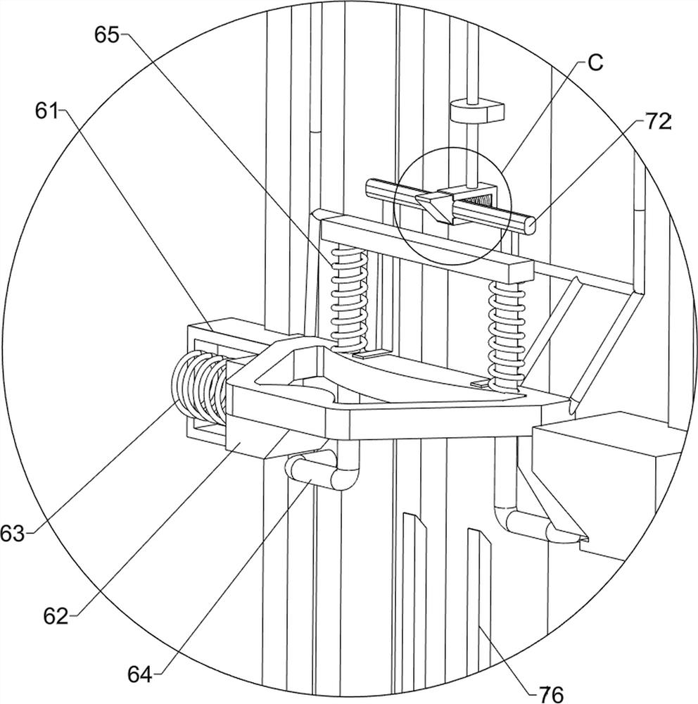
[0031] On the basis of Example 1, as Figure 7 , Figure 8 and Figure 9 As shown, it also includes a blocking component 6. The blocking component 6 includes a first sliding sleeve 61, a first wedge block 62, a fifth spring 63, a special-shaped limit rod 64 and a sixth spring 65. A sliding sleeve 61, a first wedge-shaped block 62 is slidably arranged in the first sliding sleeve 61, a fifth spring 63 is connected between the first wedge-shaped block 62 and the first sliding sleeve 61, and the pedal 47 is slidably provided with The special-shaped limit rod 64 is connected with two sixth springs 65 between the special-shaped limit rod 64 and the pedal 47 .

[0032] Also includes a clamping assembly 7, the clamping assembly 7 includes a fourth connecting rod 71, an L-shaped connecting rod 72, a second sliding sleeve 73, a second wedge-shaped block 74, a seventh spring 75 and an L-shaped limit rod 76, The outer side of the restricting plate 48 is slidably provided with a fourth ...


PUM


Abstract

The invention relates to a placing box, in particular to a multifunctional textile placing box. The invention aims to solve the technical problem of providing the multifunctional textile placing box,and according to the multifunctional textile placing box, textiles can be fixedly placed in a transparent box body, and the textiles can be directly touched by hands. The multifunctional textile placing box comprises a support, a cover plate, clamping assemblies and a material taking assembly, wherein a glass cabinet is installed at the top of the support; the cover plate is rotationally arrangedat the top of the glass cabinet; the clamping assemblies are arranged at two sides of the glass cabinet; and the material taking assembly is arranged at the lower part of the glass cabinet. Accordingto the textile placing box, the effect that the textiles can be fixedly placed in the box body, and people can directly see the textiles from the outer side and can directly touch the textiles with hands is achieved, people can directly place the textiles in the placing box through the cover plate, and the textiles are clamped through L-shaped clamping rods.

Description

technical field [0001] The invention relates to a storage box, in particular to a multifunctional textile storage box. Background technique [0002] Textiles are a product made of fibers through a series of processing and weaving, including single yarn, strands, woven fabrics, knitted fabrics, braided fabrics, etc. Textiles of different materials have different values. When people buy textiles, they often Determine the price according to the material. [0003] At present, when selling textiles in some stores, they hang the textiles directly on the hangers for customers to appreciate directly. However, in the long run, textiles are directly exposed to the air, which will be contaminated with a lot of dust and easily cause damage. If the textiles are placed In the cabinet, when customers want to identify the material of the textiles, they need to take out the textiles, which is very troublesome. When placing the textiles, the shopkeeper also needs to fix the textiles so that ...

Claims


Application Information

Patent Timeline
Patent Type & Authority Applications(China)
IPC IPC(8): B65D25/10B65D81/07
CPCB65D25/101B65D81/07
Inventor 李敏
Owner NANJING HANXIYUE AUTOMATION TECH CO LTD
Why Eureka
Try Eureka