Automatic beverage filling equipment

An automatic and canning technology, applied in packaging, liquid bottling, transportation and packaging, etc., can solve problems such as bottle displacement, and achieve the effect of avoiding waste and preventing displacement

Active Publication Date: 2021-01-08
山东美果来食品有限公司
View PDF8 Cites 16 Cited by
  • Summary
  • Abstract
  • Description
  • Claims
  • Application Information

AI Technical Summary

Problems solved by technology

[0005] In order to overcome the shortcomings of the existing technology that the bottle is prone to displacement during the conveying process, and it is necessary to manually release the beverage and stop the beverage from flowing out, the technical problem is to provide an automatic beverage canning that is not easy to cause the displacement of the bottle and can automatically fill the beverage equipment

Method used


Image

  • Automatic beverage filling equipment
  • Automatic beverage filling equipment
  • Automatic beverage filling equipment

Examples


Embodiment 1

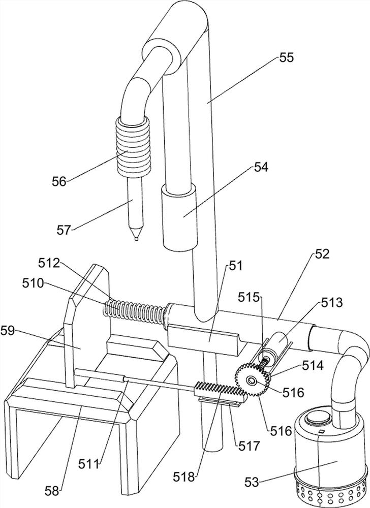
[0024] A beverage automatic canning equipment, such as Figure 1-4 As shown, it includes a base 1, a worktable 2, a feeding device 3, a canned box 4, an opening and closing device 5 and a lifting device 6, the top of the base 1 is provided with a workbench 2, the top of the base 1 is provided with a feeding device 3, and the base 1 A canned box 4 is arranged on the left side of the top, a square groove is opened on the right front side of the top of the canned box 4, an opening and closing device 5 is arranged on the top of the base 1, and a lifting device 6 is arranged on the workbench 2.

[0025] When people need to use this equipment, first people place the bottle on the feeding device 3, and pour the beverage into the canning box 4, then the opening and closing device 5 and the feeding device 3 can be started, so that the opening and closing device 5 and the feeding device The device 3 operates, so that the feeding device 3 drives the lifting device 6 to operate, and the f...

Embodiment 2

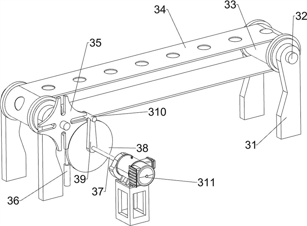
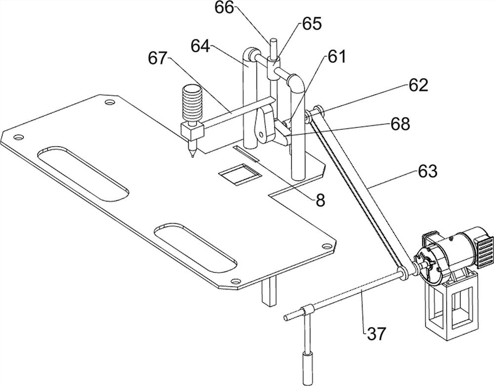
[0033] On the basis of Example 1, such as Figure 5 with Image 6 As shown, it also includes a guide sleeve 7, an L-shaped frame 9, a third connecting rod 10, and a second cam 11. The rear side of the top of the base 1 is provided with a guide sleeve 7, and the rear side of the workbench 2 has a square hole 8. The guide sleeve 7. The upper sliding type is provided with an L-shaped frame 9, and the L-shaped frame 9 slides on the square hole 8 of the workbench 2. The right end of the L-shaped frame 9 is provided with a third connecting rod 10, and the third connecting rod 10 and the first slide block 59 The rear side is connected, the rotating rod 62 is provided with a second cam 11, the second cam 11 cooperates with the L-shaped frame 9, and the second cam 11 is located at the front side of the first cam 68.

[0034] When the rotating rod 62 rotates, the rotating rod 62 drives the second cam 11 to rotate, and when the most convex part of the first cam 68 contacts the slide bar...


PUM


Abstract

The invention relates to filling equipment, particularly relates to automatic beverage filling equipment and provides automatic beverage filling equipment capable of enabling bottles to be not prone to displacement and automatically filling beverages. The automatic beverage filling equipment comprises a base, a feeding device, a filling box, an opening and closing device and a lifting device, wherein a workbench is arranged at the top of the base; the feeding device is arranged at the top of the base; the filling box is arranged at the top of the base; a square groove is formed in the fillingbox; the opening and closing device is arranged at the top of the base; and the lifting device is arranged on the workbench. According to the automatic beverage filling equipment, the feeding device is capable of achieving intermittent leftward movement of the bottles; then the opening and closing device and the lifting device cooperate to intermittently fill the beverages into the bottles; a second connecting rod can drive a discharging pipe to move up and down; the lower part of the discharging pipe moves into bottles, so that the beverages can be better filled into the bottles; meanwhile, the automatic beverage filling equipment is also capable of preventing the beverages from flowing out of the bottles during infusion, so that the waste is avoided.

Description

technical field [0001] The invention relates to a canning equipment, in particular to an automatic beverage canning equipment. Background technique [0002] Beverages are quantitatively packaged for direct drinking or brewing or brewing with water in a certain proportion. Beverages can also be divided into beverage concentrates or solid forms. Its function is to quench thirst and replenish energy. [0003] The existing large-scale automated beverage filling system requires a large area and high production capacity. It is mainly composed of semi-automatic cup feeding, automatic filling, and automatic labeling. It is mainly used for mass production and is not suitable for small batches of personalized real-time Production needs, while the existing small-batch production basically uses semi-automatic filling of beverages, which requires manual release and stop of beverage outflow, and there is also a beverage filling device that when the beverage is poured into the bottle, the ...

Claims


Application Information

Patent Timeline
Patent Type & Authority Applications(China)
IPC IPC(8): B67C3/26B67C3/24
CPCB67C3/26B67C3/24
Inventor 夏明华
Owner 山东美果来食品有限公司
Why Eureka
Try Eureka