Electronic kiln with furnace side observation function

A hearth and side technology, applied in the field of electronic kilns, can solve the problems of broken rollers, prolong maintenance time, waste of human, financial and material resources, etc., and achieve the effect of avoiding trouble

Active Publication Date: 2021-10-08
SUZHOU HUIKE EQUIP CO LTD
View PDF14 Cites 0 Cited by
  • Summary
  • Abstract
  • Description
  • Claims
  • Application Information

AI Technical Summary

Problems solved by technology

However, it is often difficult or even impossible to see the real situation in the lengthy hearth with the help of observation windows with simple structure to the lookout in the length direction of the furnace. It is hoped that situations such as deviation of the sagger, congestion, and broken rollers will miss the opportunity to eliminate the fault in time and cause more trouble. In severe cases, the product will be scrapped and the furnace will cause greater faults Maintenance costs, prolonging maintenance time, affecting production efficiency, wasting human, financial and material resources, etc.
[0004] Theoretically speaking, setting an observation window at a reasonable position on the side of the furnace body can eliminate the aforementioned technical problem of not being able to see clearly the situation in the furnace. Large, the atmosphere in the furnace will be affected, and it is considered that the problem of high temperature resistance of the observation window itself is difficult to solve, as well as the simplicity of its own structure and convenient operability, etc. are unavoidable technical problems
However, the applicant believes that the above-mentioned views in the current industry are essentially caused by technical bias, and this technical bias has to a large extent adversely restricted or even restricted attempts to improve

Method used


Image

  • Electronic kiln with furnace side observation function
  • Electronic kiln with furnace side observation function
  • Electronic kiln with furnace side observation function

Examples


Embodiment Construction

[0020] In order to understand the technical essence and beneficial effects of the present invention more clearly, the applicant will describe in detail the following examples, but the descriptions of the examples are not intended to limit the solutions of the present invention. Equivalent transformations that are only formal but not substantive should be regarded as the scope of the technical solution of the present invention.

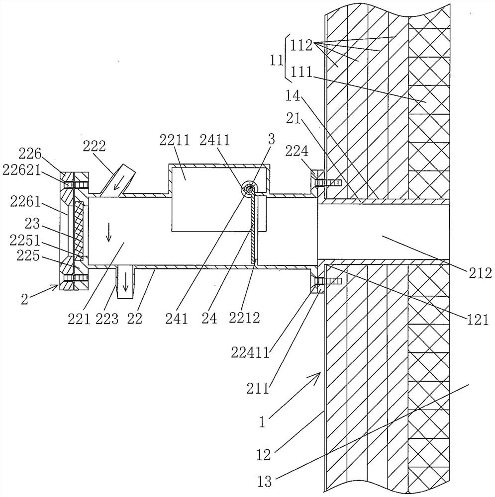
[0021] In the following descriptions, the concepts of directionality or orientation of up, down, left, right, front and back that may be involved are based on figure 1 The current position is a reference, so it cannot be understood as a special limitation on the technical solution provided by the present invention.

[0022] See figure 1 , shows the furnace body 1, the furnace body 1 includes a pair of furnace wall linings 11, the pair of furnace wall linings 11 are located in the furnace shell 12 and parallel to each other in the length direction, the...


PUM


Abstract

An electronic kiln with the function of observing the side of the furnace, including a furnace body, the furnace body includes a pair of furnace wall linings, the pair of furnace wall linings are located in the furnace shell and parallel to each other in the length direction, between the pair of furnace wall linings The space constitutes the furnace, and features: at least one of the pair of furnace wall linings is provided with observation tube installation holes at intervals along the length direction of the furnace wall linings, and the observation tube installation holes face one end of the furnace shell The installation hole of the furnace shell opened on the furnace shell communicates with the outside world, and the end of the observation tube installation hole facing the furnace communicates with the furnace; The side observation mechanism of the furnace. With the aid of the observation mechanism on the side of the furnace, the situation of the furnace can be observed as needed, so as to find in time the situations in the furnace such as deviation, pile up, tipping and broken rollers in the furnace, and it is beneficial to take timely disposal measures to win Take your time and avoid further trouble.

Description

technical field [0001] The invention belongs to the technical field of kilns, and in particular relates to an electronic kiln with the function of observing the side of a furnace. Background technique [0002] As known in the industry, the production of electronic powder, electronic components, silicon nitride, aluminum nitride, silicon carbide, lithium battery cathode materials, ceramics, phosphor powder, rare earth materials and magnetic materials must be sintered by means of kilns. Therefore, electronic kilns play an indispensable and important role in the production of high-end electronic products. Because the electronic kiln drives the sintered product with both roller rod driving and push plate driving, the industry distinguishes it as roller table type electronic kiln and push plate electronic kiln. Typical publications of the former are: CN208059547U (lithium battery material sintering roller furnace), CN210802019U (a kiln), CN111351347A (a double-layer roller furna...

Claims


Application Information

Patent Timeline
Patent Type & Authority Patents(China)
IPC IPC(8): F27B9/40F27D21/02
CPCF27B9/40F27D21/02
Inventor 周晓铿吕华博曹志军董安伟
Owner SUZHOU HUIKE EQUIP CO LTD
Why Eureka
Try Eureka