
Photoresist coating system

A glue coating and lithography technology, applied in the field of photoresist coating systems, can solve the problems of pipeline blockage, failure to spray, and lengthened production cycle, so as to reduce the rework rate and reject rate, reduce production costs, and improve The effect of production efficiency

Inactive Publication Date: 2009-09-09
SEMICON MFG INT (SHANGHAI) CORP +1
View PDF4 Cites 0 Cited by
  • Summary
  • Abstract
  • Description
  • Claims
  • Application Information

AI Technical Summary

Problems solved by technology

In addition, in addition to the switch status of each component, there will be some other mechanical failures in the glue machine, such as pipeline blockage, etc., which will also cause the amount of photoresist to be sprayed less, or even not sprayed.
[0006] However, the existing gluing machine cannot monitor the actual amount of photoresist sprayed, and the verification of the actual sprayed amount can only be realized by sampling the thickness of the thin layer of photoresist after the gluing is completed.
During random testing, it was found that the thickness of the photoresist thin layer deviates, and then reworked, resulting in a longer production cycle and affecting production efficiency
For the problematic wafers that have not been sampled, the subsequent processes will continue, resulting in scrapped wafers and increased costs.
In addition, the thickness of the photoresist thin layer is sampled after the coating is completed, and the accuracy of the thickness of the photoresist thin layer and the repeatability between batches cannot be guaranteed.

Method used

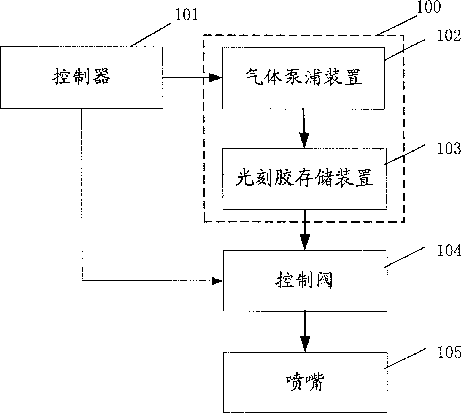
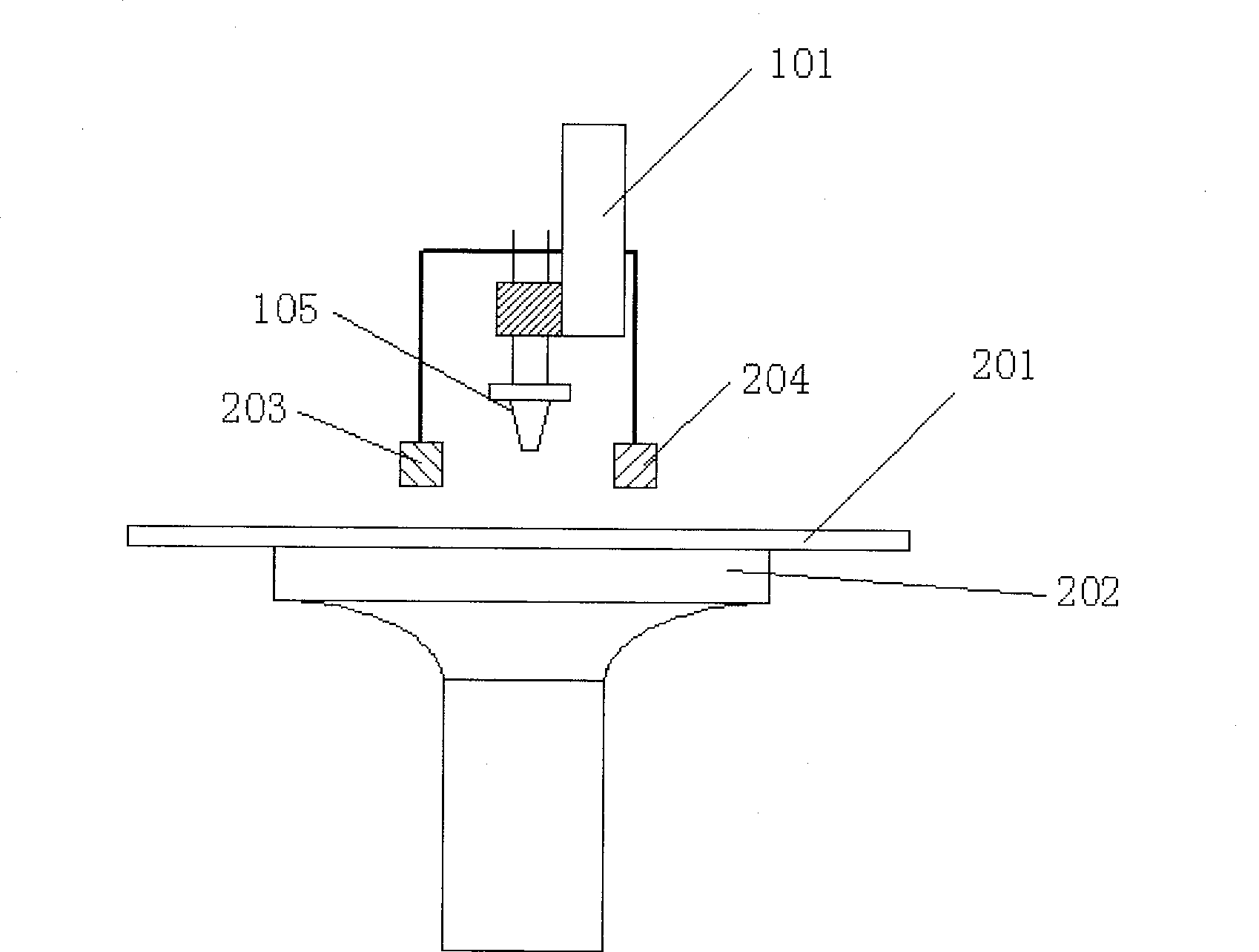
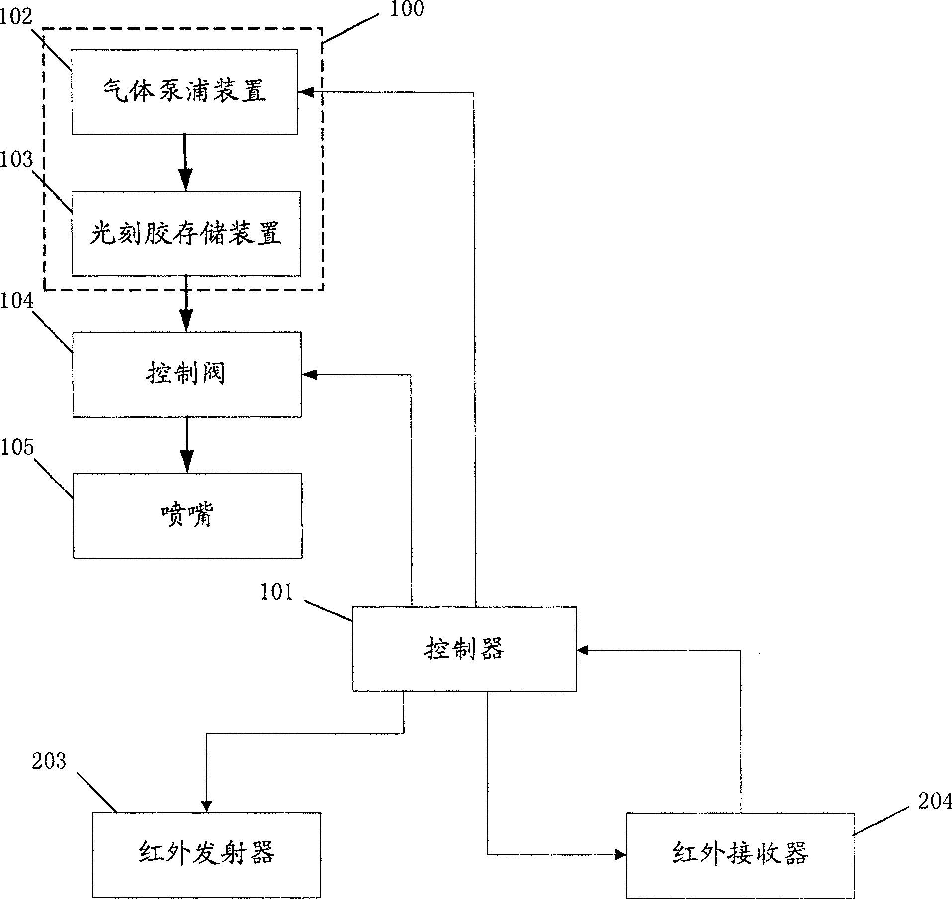

Image

  • Photoresist coating system
  • Photoresist coating system
  • Photoresist coating system

Examples


Embodiment Construction

[0027] In order to make the above objects, features and advantages of the present invention more comprehensible, specific implementations of the present invention will be described in detail below in conjunction with the accompanying drawings.

[0028] During the coating process of photoresist, the amount of photoresist sprayed may deviate easily due to air bubbles, pipeline aging or mechanical failure. However, the existing photoresist coating system has no means of monitoring the spraying results, and only relies on the photoresist after coating. Sampling measurement of the thickness of the thin layer of resist to verify whether the spraying amount of photoresist is normal, and the deviation of the actual spraying amount cannot be found in time, resulting in the difference in the spraying amount of photoresist (or the thickness of the thin layer of photoresist) between batches. Repeatability is not guaranteed, and the rework rate and scrap rate are also high.

[0029] The ph...


PUM


Abstract

A photoresist coating system is disclosed. The system includes a controller, a glue supply device and a nozzle. Spray onto the wafer; the system also includes a spraying detection device, the detection device includes an infrared emitter and an infrared receiver arranged on both sides below the nozzle, and the infrared emitter receives the emission sent by the controller Infrared rays are emitted after the signal, and the infrared receiver receives the infrared rays after receiving the receiving signal sent by the controller, and feeds back the received infrared signal to the controller, and the controller obtains according to the interruption time of the received infrared signal actual spraying time. The invention can detect abnormal photoresist spraying phenomenon in time, improves the repeatability between batches, reduces rework rate and scrap rate, and improves production efficiency.

Description

technical field [0001] The invention relates to the technical field of semiconductor manufacturing, in particular to a photoresist coating system. Background technique [0002] In the semiconductor manufacturing process, the photolithography process has always been considered the most critical step in the manufacture of integrated circuits. It needs to be used many times throughout the process. Its stability, reliability and process yield have a great impact on product quality and yield. and cost have a significant impact. The photolithography process is a complex process, the essence of which is to copy the temporary circuit structure in the form of graphics to the wafer that will be etched and ion-implanted in the future: first, a photosensitive layer is formed on the wafer by using a Spin Coater. Material—a thin layer of photoresist, and then irradiate parallel light on the thin layer of photoresist through a mask to make it exposed and deteriorated, and finally use a de...

Claims


Application Information

Patent Timeline
Patent Type & Authority Patents(China)
IPC IPC(8): G03F7/16
Inventor 黄良志周瑶亮
Owner SEMICON MFG INT (SHANGHAI) CORP
Learn More