Attaching structure and attaching method of display module

A display module and liquid crystal display module technology, applied in nonlinear optics, instruments, optics, etc., can solve problems such as easy occurrence of air bubbles in blind hole areas, high defective products, and increased production process, so as to reduce attached air bubbles Volume, reduced foaming rate, and low equipment cost

Pending Publication Date: 2021-01-08
SHENZHEN TXD TECH CO LTD
View PDF0 Cites 2 Cited by
  • Summary
  • Abstract
  • Description
  • Claims
  • Application Information

AI Technical Summary

Problems solved by technology

In the bonding process of display modules, the OCA full bonding process is generally used, that is, the OCA glue covers the entire cover plate and the upper polarizer above the liquid crystal glass for bonding, and then defoaming is performed after bonding, but the blind hole area is easy to Bubbles appear, resulting in high levels of defective products
Another display module manufacturer uses high-fluidity OCA glue for lamination, and then defoams through high temperature and high pressure to reduce the probability of air bubbles in the blind hole area, but the purchase cost of high-fluidity OCA glue is much higher than that of ordinary OCA glue. And the storage conditions are strict, and it needs to be stored at -10-0°C. After the lamination is completed, a special defoamer needs to be used for high-temperature and high-pressure defoaming. The defoaming time is 30-60 minutes. It can be seen that high-fluidity OCA glue is used for lamination , resulting in cumbersome production process, increased production process, and high cost

Method used


Image

  • Attaching structure and attaching method of display module
  • Attaching structure and attaching method of display module

Examples


Embodiment Construction

[0030] The present invention will be described in detail below in conjunction with the accompanying drawings and specific embodiments.

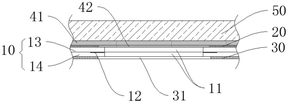
[0031] The present invention provides a bonding structure of a display module, such as figure 1 As shown, the bonding mechanism of the display module includes: a liquid crystal glass 10 , an upper polarizer 20 , a lower polarizer 30 , a first OCA adhesive layer 41 , a second OCA adhesive layer 42 and a cover plate 50 . Wherein, the liquid crystal glass 10 is provided with a blind hole 11, and the edge of the blind hole 11 is provided with a circle of light-shielding area 12, and the light-shielding area 12 plays the role of light-shielding to prevent the liquid crystal glass 10 from passing through the blind hole 11. light leak. Specifically, the liquid crystal glass 10 includes: a CF glass 13, a TFT glass 14 and a liquid crystal (not shown) disposed between them, the CF glass 13 is disposed above the TFT 14 glass, and the light-shielding ar...


PUM


Abstract

The invention discloses an attaching structure and attaching method of a display module. Theattaching structure comprises liquid crystal glass, an upper polaroid, a lower polaroid, a first OCA adhesive layer, a second OCA layer and a cover plate; a blind hole is formed in the liquid crystal glass; the edge of the blind hole is provided with a circle of shading region; the upper polaroid and the lower polaroid are respectively arranged above and below the liquid crystal glass; the upper polaroid and the lower polaroid are respectively provided with a first through hole and a second through holecorresponding to the blind hole; the vertical projections of the hole edges of the first through hole and the second through hole fall onto the shading region; the first OCA layer is arranged above the upper polaroid; the second OCA layer is attached to the liquid crystal glass and fills the first through hole; and the cover plate is arranged above the first OCA layer. According to the attachingmethod of the display module, common OCA is adopted for attaching, the second OCA layer is attached to the interior of the first through hole of the upper polaroid in advance, the volume of attachingbubbles is reduced, the foaming rate is greatly reduced, the production process is simple, the production process is short, and the yield is greatly increased.

Description

technical field [0001] The invention relates to the technical field of bonding production of display modules, in particular to a bonding structure and bonding method of display modules. Background technique [0002] OCA (Optically Clear Adhesive) is an optically transparent layer of special substrate-free double-sided adhesive, which is a special adhesive for bonding transparent optical components (such as lenses, etc.). It is required to be colorless and transparent, with light transmittance above 90%, good bonding strength, curable at room temperature or medium temperature, and small curing shrinkage. It is widely used in the bonding process of the cover plate of the display module and the liquid crystal glass. In the bonding process of display modules, the OCA full bonding process is generally used, that is, the OCA glue covers the entire cover plate and the upper polarizer above the liquid crystal glass for bonding, and then defoaming is performed after bonding, but the...

Claims


Application Information

Patent Timeline
Patent Type & Authority Applications(China)
IPC IPC(8): G02F1/13G02F1/1335
CPCG02F1/1303G02F1/133528
Inventor 罗俊骆志锋卢建灿尹宗兵奉福周
Owner SHENZHEN TXD TECH CO LTD
Why Eureka
Try Eureka