
A flexible display bonding device

A technology for flexible display screens and bonding devices, which is applied to identification devices, instruments, etc., can solve problems such as unstable connections, lower production efficiency, and increased difficulty of bonding, so as to reduce maintenance difficulty, improve bonding effects, and operate simple and efficient effect

Active Publication Date: 2021-10-01
JIANGSU SHIBANG FLEXIBLE ELECTRONICS RES INST CO LTD
View PDF8 Cites 0 Cited by
  • Summary
  • Abstract
  • Description
  • Claims
  • Application Information

AI Technical Summary

Problems solved by technology

[0002] A flexible display is a product that is bonded to each other by a flexible component and a corresponding display device under the action of an external force. During the bonding process of the flexible component and the display device, the bonding of the flexible component to the edge of the display device is particularly important, because the flexibility Due to the characteristics of the components, when the points far from the edge are stressed, the flexible components will be deformed. If the edges are not well fitted, the flexible components will be unstable or misaligned on the flexible display.
[0003] The existing patent No. CN103009774A proposes a bonding device and a bonding method of a flexible film, which has the function of improving the alignment accuracy of the center position of the bonded device, but it lacks the effect of strengthening the bond between the flexible component and the edge of the display device The structure, focusing on the center of the flexible component will easily lead to deformation of the flexible component due to its own flexibility, resulting in errors between the flexible combination and the edge of the display device, making it more difficult to fit
[0004] The existing patent number CN107945665B proposes a flexible display bonding method and flexible display bonding equipment, which has the advantages of greatly reducing the difficulty of operation and improving production efficiency, but its contact surface with the flexible component during the bonding operation If it is too large, the pressure effect will increase, and the pressure needs to be released slowly during the bonding process to avoid crushing the flexible components, which will reduce the production efficiency

Method used


Image

  • A flexible display bonding device
  • A flexible display bonding device
  • A flexible display bonding device

Examples


Embodiment Construction

[0035]The following will clearly and completely describe the technical solutions in the embodiments of the present invention with reference to the accompanying drawings in the embodiments of the present invention. Obviously, the described embodiments are only some, not all, embodiments of the present invention. Based on the embodiments of the present invention, all other embodiments obtained by persons of ordinary skill in the art without making creative efforts belong to the protection scope of the present invention.

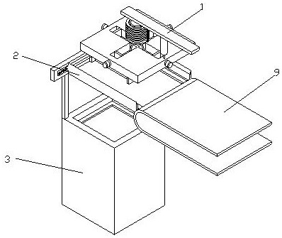
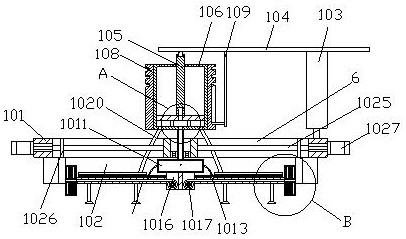
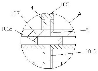
[0036] see Figure 1-7 , a flexible display bonding device, comprising a bonding mechanism 1, a feeding mechanism 2 and an installation mechanism 3, the bonding mechanism 1 is arranged above the feeding mechanism 2, and the feeding mechanism 2 is arranged above the installation mechanism 3, Fitting mechanism 1 comprises fitting board 101, and the bottom surface of fitting board 101 is movably installed limit frame 102, and limit frame 102 is made up of four rec...


PUM


Abstract

The invention relates to the technical field of display devices, and discloses a flexible display bonding device, which includes a bonding mechanism, a feeding mechanism and an installation mechanism. The bonding mechanism is arranged above the feeding mechanism, and the feeding mechanism is arranged on the installation mechanism. Above, the fitting mechanism includes a fitting plate, and the bottom surface of the fitting plate is movably installed with a limit frame. The limit frame is composed of four rectangular plates and the four rectangular plates are distributed in a rectangle. There is a telescopic device above the right side of the fitting mechanism. The top surface of the fitting mechanism is fixedly connected with the transmission shaft of the telescopic equipment. The top surface of the telescopic equipment is fixedly connected with a connecting plate. The bottom surface of the connecting plate corresponding to the center of the fitting mechanism is fixedly connected with a pull rod through a universal ball. Through the setting of the fitting mechanism, the During the lamination operation, let the lamination wheel rotate and squeeze along the edge of the display device and the flexible component, and concentrate the pressure of lamination on the edge of the display device and the flexible component, avoiding pressure dispersion that leads to poor lamination effect and efficiency low problem.

Description

technical field [0001] The invention relates to the technical field of display devices, in particular to a flexible display bonding device. Background technique [0002] A flexible display is a product that is bonded to each other by a flexible component and a corresponding display device under the action of an external force. During the bonding process of the flexible component and the display device, the bonding of the flexible component to the edge of the display device is particularly important, because the flexibility Due to the characteristics of the components, when a point far from the edge is stressed, the flexible component will be deformed. If the edge is not properly fitted, the connection of the flexible component on the flexible display will be unstable or misplaced. [0003] The existing patent No. CN103009774A proposes a bonding device and a bonding method of a flexible film, which has the function of improving the alignment accuracy of the center position of...

Claims


Application Information

Patent Timeline
Patent Type & Authority Patents(China)
IPC IPC(8): G09F9/30
CPCG09F9/301
Inventor 萧滔
Owner JIANGSU SHIBANG FLEXIBLE ELECTRONICS RES INST CO LTD
Learn More