Ultrasonic horn with enlarged distal end portion

a technology of ultrasonic horn and distal end portion, which is applied in the field of ultrasonic horn and ultrasonic hand piece, can solve the problems of x-ray picture, which is two-dimensional image, requires a significantly high level of skill, and the operation of taking an x-ray picture requires suspension

Inactive Publication Date: 2010-05-13
STRYKER CORP
View PDF6 Cites 39 Cited by
  • Summary
  • Abstract
  • Description
  • Claims
  • Application Information

AI Technical Summary

Benefits of technology

[0011]An object of the present invention is to provide an ultrasonic horn and an ultrasonic hand piece, as well as a...

Problems solved by technology

Since a radicle of a nerve is present adjacent to the narrow area and is very close to the cortical bone, breaking through the cortical bone with the drill may lead to damage on the surrounding nerves or vessels.
However, appropriately forming the guide hole relying on the X-ray pictures, which are two-dimensional images, requires a significantly high level of skill.
Further, taking an X-ray picture requires suspension of the operation.
Irrespective of the lower cutting efficiency as compared to...

Method used


Image

  • Ultrasonic horn with enlarged distal end portion
  • Ultrasonic horn with enlarged distal end portion
  • Ultrasonic horn with enlarged distal end portion

Examples


Embodiment Construction

[0030]Embodiments of the present invention will now be described with reference to the drawings.

(Ultrasonic Hand Piece)

[0031]First, an ultrasonic hand piece according to an embodiment of the present invention will be described with reference to FIGS. 1 to 4.

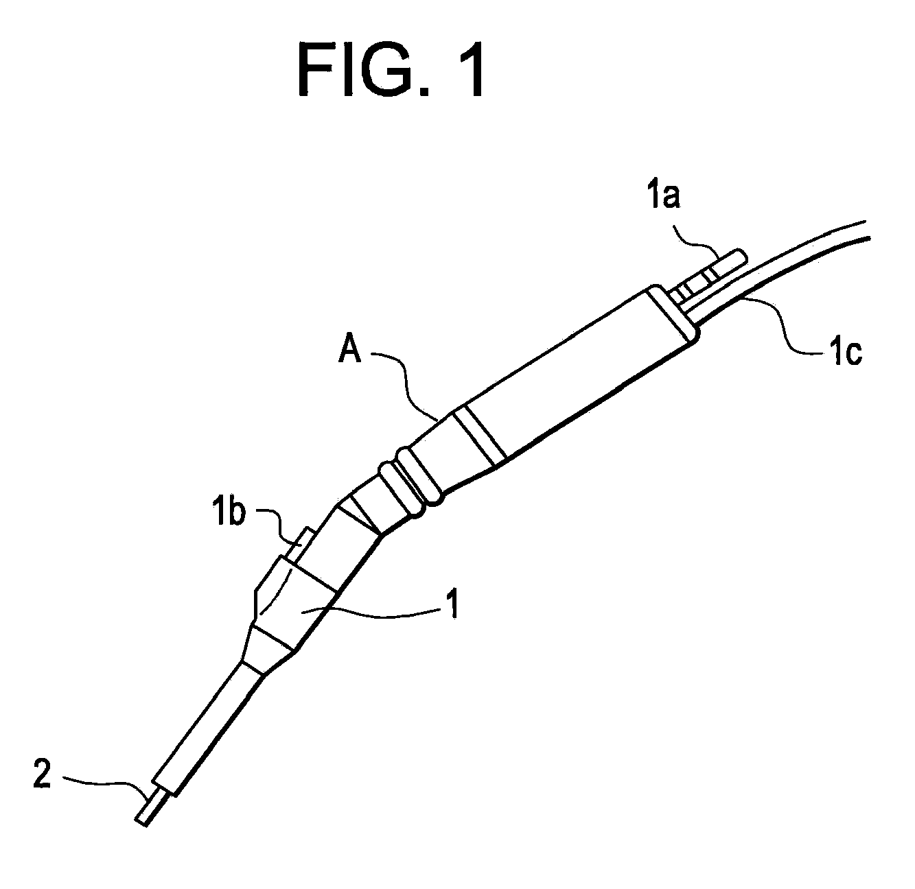
[0032]FIG. 1 illustrates an ultrasonic hand piece according to an embodiment of the present invention.

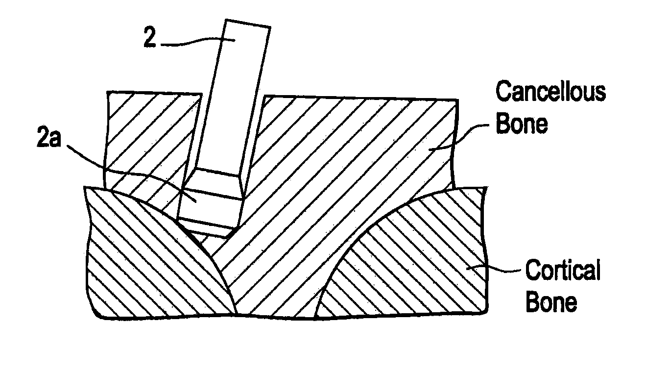
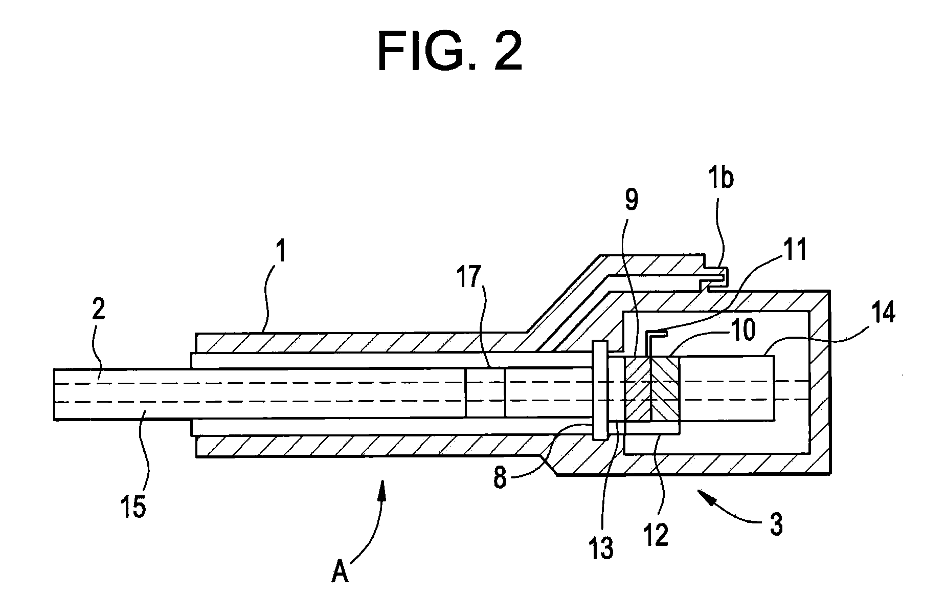
[0033]Referring to FIG. 1, outer cylindrical portion 1 houses ultrasonic vibration mechanism 3 (see FIG. 2) that includes a vibrator, such as a magnetostrictive type or an electrostrictive type, that outputs ultrasonic waves of a predetermined frequency. Horn 2 is inserted into outer cylindrical portion 1 at one end thereof. Horn 2 is adapted to cut hard living tissue, such as a bone, with a distal end structure thereof by the aid of vibration that is transmitted from ultrasonic vibration mechanism 3. Irrigation liquid, pieces of living tissue cut into fragments, etc. are sucked out to a tube, not shown, via connection 1a. Irriga...


PUM


Abstract

An ultrasonic horn includes a main body portion and a distal end structure formed at a distal end of the main body portion, the ultrasonic horn being adapted to be used to cut living tissue. The largest outer diameter of a portion of the ultrasonic horn is in the distal end structure, the portion being inserted into the living tissue when the living tissue is cut.

Description

[0001]The present application is based on, and claims priority from, J.P. Application No. 2008-115286, filed on Apr. 25, 2008, the disclosure of which is hereby incorporated by reference herein in its entirety.BACKGROUND OF THE INVENTION[0002]1. Field of the Invention[0003]The present invention relates to an ultrasonic horn and an ultrasonic hand piece, and in particular, relates to an ultrasonic horn and an ultrasonic hand piece suitable for cutting living bone tissue.[0004]2. Description of the Related Art[0005]In a conventional orthopedic operation of a spine or a cervical spine, a treatment including; (a) fixing a plurality of pedicle screws to centrums and (b) coupling the pedicle screws to a plate in order to fix the centrums together has been commonly used. In order to fix a pedicle screw to a centrum, a doctor normally cuts and removes the vertebral arch from the centrum, and then uses a drill to form a guide hole in the cancellous bone of the pedicle into which a pedicle sc...

Claims


Application Information

Patent Timeline
IPC IPC(8): A61B8/14
CPCA61B17/1671A61B17/320068A61B2217/005A61B2017/320096A61B2017/320072A61B2017/320098A61B2017/32007A61B2017/320073
Inventor OTA, HIDEFUMISUZUKI, KAZUYUKI
Owner STRYKER CORP
Why Eureka
Try Eureka