Gas concentrator with improved water rejection capability

a technology of gas concentrator and water rejection capability, which is applied in the direction of filtration separation, auxillary pretreatment, separation process, etc., can solve the problems of less mitigative options or design choices against contamination and other wear and tear effects, and complex gas flow control through the compressor and the beds in the gas separation cycle. to avoid efficiency and power loss

Active Publication Date: 2010-08-24
INOGEN SA
View PDF19 Cites 46 Cited by
  • Summary
  • Abstract
  • Description
  • Claims
  • Application Information

AI Technical Summary

Benefits of technology

[0013]A preferred embodiment of the present invention is a gas concentrator with a membrane dryer combined with the gas separation section to avoid efficiency and power loss, and still achieve the needed air drying. The novel concentrator utilizes the waste gas of the gas separation section to sweep the membrane dryer system. In this configuration, approximately 90% of the feed gas can be used as sweep, since only a small amount of product gas is taken for delivery to the patient. The integration of the gas separation cycle waste gas and the membrane air dryer also enables the sweep of the membrane to be dynamically controlled, if necessary to control water removal, since the sweep flow is not dictated by a fixed orifice in the membrane dryer housing, but rather by the controllable valve system of the pressure swing adsorption unit.
[0017]In another embodiment, the concentrator may include a specialized desiccant layer of adsorbent disposed before the high performance air separation adsorbent to further suppress the amount of water or other impurities, such as CO2, allowed to enter the adsorbent that is important to air separation.
[0018]In another embodiment, the concentrator may include a condenser and water trap utilized in combination with the membrane dryer and / or a specialized layer of adsorbent disposed before the high performance air separation adsorbent to further suppress the amount of water or other impurities, such as CO2 allowed to enter the adsorbent that is important to air separation.
[0019]In one embodiment, the membrane dryer further acts as an exhaust muffler to decrease acoustic noise output from the concentrator. In another embodiment, the dew-point of the feed gas is monitored after the dryer, and the amount of sweep gas to the dryer is controlled to achieve a target dew-point level.
[0020]In another embodiment, the purge flow from the membrane dryer may be connected to the vacuum port of a pump in a VPSA system to enhance the pressure gradient across the membrane.

Problems solved by technology

Such systems are known in the art, and it is appreciated that the gas flow control through the compressor and the beds in a gas separation cycle is complex and requires precise timing and control of parameters such as pressure, flow rate, and temperature to attain the desired oxygen concentration in the product gas stream.
Thus portable concentrators involve a significant amount of miniaturization, leading to smaller, more complex designs compared to stationary units.
System size, weight and complexity may lead to fewer mitigative options or design choices against contamination and other wear and tear effects.
One particular challenge of portable concentrator design is that the adsorbent beds must by necessity be small, yet capable of producing an adequate quantity of product gas.
Since the adsorbent beds are optimized for maximum performance from a reduced size, any significant decrease in capacity of the beds over time can result in decreased product purity.
One contributing factor that can lead to a decrease in bed capacity is the adsorption of impurities that do not completely desorb during normal process operation, leading to the accumulation and retention of impurities in the beds.
Portable concentrators, by the nature of their application, are more likely to be exposed to a wide range of operating conditions including high humidity environments and / or rapid temperature changes that could result in the need for more sophisticated water rejection capabilities than implemented in prior designs.
These regeneration processes are impractical in a portable concentrator.
As a result, the accumulation of adsorbed water over time results in a reduction in capacity of the beds, as fewer sites are available for nitrogen binding.
Fewer binding sites in the adsorbent bed can result in a decrease in product purity over time, and ultimately a shortened service life of the concentrator.
Many zeolites used in air separation, and in particular advanced adsorbents, particularly the high lithium containing low silica X type zeolite, are hydrophilic in their activated state and can therefore be prone to this problem.
Although highly effective air drying systems exist in other fields, most of these systems consume power, increase size and weight, or reduce system efficiency in a manner detrimental to the stringent power consumption, size / weight, and acoustic noise level requirements of portable concentrators.
However, additional beds add significant size and weight to the concentrator, or in the case of layered beds the desiccant layer displaces volume that could otherwise be used for adsorbent used for highly efficient air separation or the volume of the process columns could be decreased accordingly, and additional power is used to compress gas through this desiccant.
The desiccants typically used for pre-drying air are also prone to deactivation during constant cycling as well as during shutdown periods, and are often regenerated via applying one of the aforementioned methods.
In some cases, the desiccant layer may be advantageous, but also might not be entirely effective at protecting the specialized adsorbents from water damage.
Traditional means of removing water such as coalescing filters and gravity water traps have limited abilities to remove water and can thereby limit the usable service life of oxygen concentrating equipment.
The varying operating and storage environments that portable concentrators may be exposed to result in design challenges that more conventional gas separation systems such as gas separation plants might not encounter and must be addressed.

Method used


Image

  • Gas concentrator with improved water rejection capability
  • Gas concentrator with improved water rejection capability
  • Gas concentrator with improved water rejection capability

Examples


Embodiment Construction

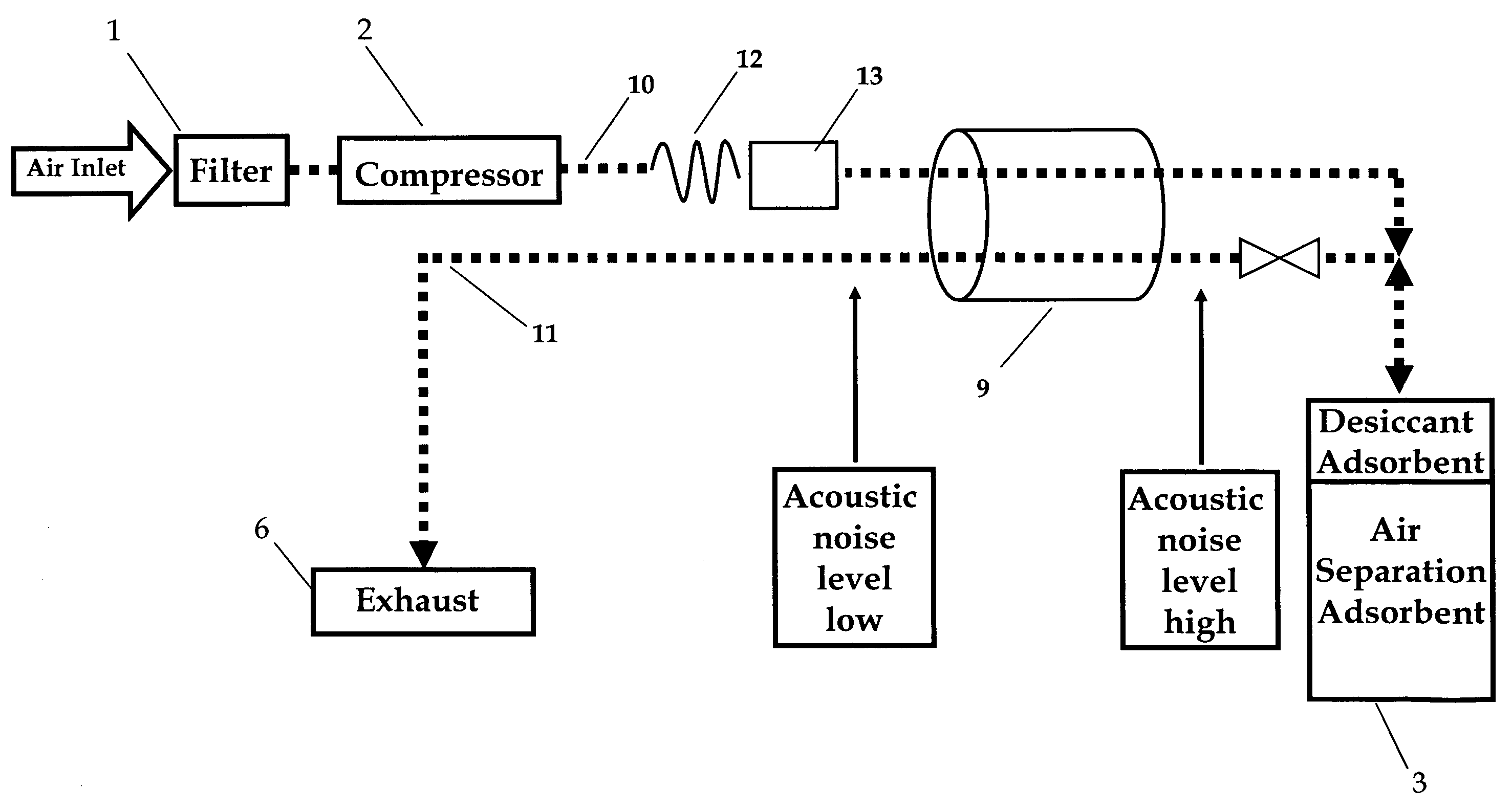
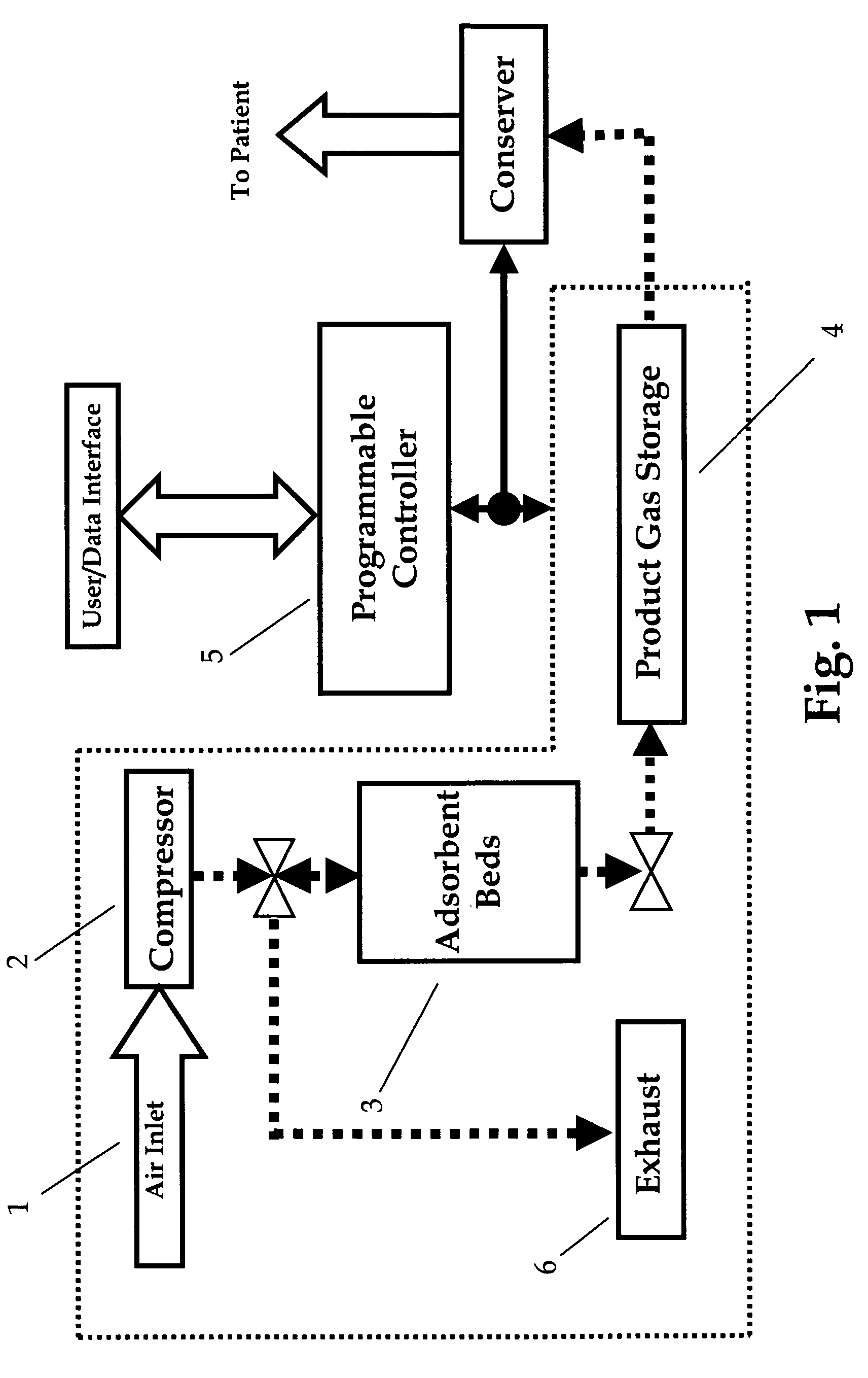
[0035]Referring to FIG. 1, general features of a gas concentrator are shown. Typically gas is drawn into the inlet through an inlet filter 1 into a compressor 2. Compressed air is then delivered (through various filters and other devices) to a gas separation section for selectively adsorbing a component of the gas. The preferred embodiments of the invention, although applicable to a variety of gas concentrator implementations, will be described in detail for the case where the inlet gas is air, and the gas separation section is PSA, VSA, VPSA or some combination thereof, utilizing adsorbent beds 3 which selectively adsorb nitrogen, producing oxygen rich product.

[0036]A variety of gas separation section cycle types and bed arrangements are known in the art, most of which can benefit from the preferred embodiments of the invention. Whatever the details of the gas separation section 3, typically product gas is accumulated in a storage device 4. Storage devices may include a tank in the...


PUM

PropertyMeasurementUnit
pressureaaaaaaaaaa
dew pointaaaaaaaaaa
temperatureaaaaaaaaaa

Abstract

A feed gas drying system is described for a PSA or VPSA oxygen concentrator. A membrane dryer is inserted into the feed gas path to the concentrator absorbent beds, such that the moisture in the feed gas is directed to a part of the dryer exposed to the concentrator exhaust, thus achieving efficient operation of the membrane dryer with no loss of concentrator feed gas.

Description

RELATED APPLICATIONS[0001]This application claims priority to U.S. Provisional application Ser. No. 60 / 861,536, filed Nov. 28, 2006FEDERALLY SPONSORED RESEARCH[0002]Not ApplicableSEQUENCE LISTING[0003]Not ApplicableBACKGROUND OF THE INVENTION[0004]1. Field of the Invention[0005]The invention generally relates to gas concentrators, and more particularly relates to a concentrator having an integral system adapted for removing moisture from compressed gas feed stream to improve the performance efficiency of adsorbent beds. The application is particularly directed to compact; portable oxygen concentrators for therapeutic use, but the principles apply to any gas concentrator utilizing adsorbent beds.[0006]2. Description of the Related Art[0007]The application of oxygen concentrators for therapeutic use is known, and many variants of such devices exist. A particularly useful class of oxygen concentrators is designed to be portable, allowing users to move about and to travel for extended p...

Claims


Application Information

Patent Timeline
Patent Type & Authority Patents(United States)
IPC IPC(8): B01D53/047
CPCB01D53/0476B01D53/229B01D2253/108B01D2256/12B01D2257/102B01D2257/80B01D2259/4145B01D2259/4533B01D2259/455
Inventor TAYLOR, BRENTONHANSEN, PETER
Owner INOGEN SA
Why Eureka
Try Eureka